Proceedings 6-th
Intern. Symposium Fresh Water from the Sea, Vol. 2. 251-240, 1978
MECHANISM AND SCALE FORMATION CONTROL IN A MSF PLANT USING AN ELECTROMAGNETIC APPARATUS
0.I.MARTYNOVA, A.S.KOPYLOV and V.F.OCHKOV
Institute for Power Engineering, Moscow, U.S.S.R.
Results of using an electromagnetic apparatus (e.m.a.) for purpose of scale formation control in the head preheater of an three-stage flash evaporator are given.
It allowed to double the plants operation time between cleanings of the head preheater. The rate of uniform scale formation on heat transfer surfaces drastically decreased while sludge formation rate simultaneously increased. This may, if the sludge is not properly separated, lead to some of the tubes plugging. An mathematical model is layed out, explaining the influence of an inserted e.m.a. on the mechanism of scale and sludge formation processes in the heat transfer system.
The usual problems of scale control by traditional
chemical treatment methods are especially difficult to cope with in small
capacity evaporation plants due to some peculiarities, connected with their
operation automatization, monitoring etc. At the same time, scale formation
rates in plants of this special type can be rather efficiently decreased by
means of some physical methods – mainly magnetic and supersound
treatment both not new but again and again reappearing and sometimes used with
success.
The main feature of magnetic treatment – as well
known – is that prior to entering the heat transfer system, water flows
through a magnetic device with a definite magnetic field of specific configuration.
As well known, too, publications, describing this process both on. Industrial
and laboratory conditions differ widely in their results and conclusions a
theory, well enough explaining the phenomena of scale prevention by a magnetic
field has not been worked out yet. Nevertheless analysis of results, obtained
in industry and laboratory tests, show that changes taking place in scale
deposition rate on the heat transfer system as well as sludge formation rate
are due to the formation of solid particles in the e.m.a. gap; those particles
farther play the role of seed crystals. Of course, under these conditions the
scale formation rate can decrease sharply while sludge formation rate increases
simultaneously [1].
Naturally, the scale formation process can – by shifting to formation – take place under one condition only: prior to ex into the e.m.a. the treated water has to be supersaturated, example, on calcium carbonate i.e. has to exist in a metaste state [2]. However, this is a necessary but not sufficient and other factors are important; too; first of all the prese ferromagnetic corrosion products, both in colloidal and coar dispersed state in the treated water plays a dominating role netic treatment*
This paper discusses some results of installing an
e.m.a. to scale formation rate in a three stage flash evaporator the p] the
e.m.a. in the circuit being predetermined by the treated water's
supersaturation – on calcium carbonate – degree, taking into account ion
associates formation.
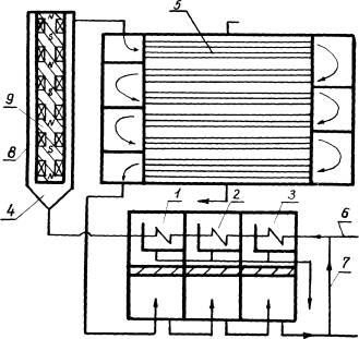
Fig. 1.
The scheme of the three-stage flash evaporator with
the e.m.a. shown on fig. 1. The initial sea water (6) salinity 17200 ppm,
alkalinity – 3.2 mg-equ/l, calcium – 10 mg-equ/l, magnesium – 60 mg-equ/l, iron
– 0,7 ppm) was mixed with the brine from the third stage
(7) in
order to assure the feedwater temperature on a constant level 28 C, passed to
the evaporator chambers condensers (1, 2, 3) and entered into the head
preheater (5). The latter was laid out as an horizontal six-passage steam
heated heat exchanger; it's initial characteristics: heat flux – 43 kw/m2;
water velocity – 1.75 m/sec; construction material-cupro-nickel
alloy; tube dimensions – 13/15 x 1600 mm; water input
temperature 58°C; water outputs temperature 75°C; steam condensate
temperature – 78°C; water flow rate –16 kg/s ; number of tube rows in the first
and sixth passages of the preheater – 4; number of tube
rows in the second, third, fourth and fifth passages – 3.
A magnetic field with a maximal intensity of 160 kA/m
was created in the circular gap of the e.m.a. between the vessel (8), a system
of six current coils and a magnetic circuit placed into a shell of
stainless steel (9).
All these data were worked out previously to the
industrial experiment under laboratory conditions on a one-tube model of the
head preheater, simulating the MSF plant [3].
Besides, before puling the e.m.a. into service
the MSF plant's efficiency without any special scale control was investigated (control
tests). The nominal output of the evaporator – 2500 kg/h, time of operation –
2000 hours. It was established;
– scale deposition in the head preheater initiates
heating steam condensate temperature rise, the linear dependance being:
tk = t°k + k . T (°C),
where (1)
t°k = 78°C – initial steam
condensate temperature in the head preheater; T – operation time of the plant;
K = 0.0085°C – coefficient of scale deposition rate in the head preheater.
Approximately 8% of the first passage heat transfer tubes were plugged by
sludge.
Experiments with the same three stage flash
evaporator and a put in e.m.a. were carried out under the same conditions;
nominal output – 2500 kg/h, operation time 2000 hours with an
intermediate inspection after 1400 h. of operation. It was clear, that the
formation of salid particles took place in two different ways:
– sludge was farmed in a greater amount, resulting in
plugging of some tubes;
– uniform deposition of dense crisalline scale
on the internal surfaces of the heat transfer tubes, tube plate and surfaces of
the channel's bends. But the scale formation rate was less than without the
e.m.a.» resulting in a decrease of the coefficient K in equation (1) down to
0.0040°C/h. After 2000 h. of operation in this case the head preheater
condensate temperature was 86 C while after the control tests, i.e. without an
e.m.a. this temperature was as high as 95°C. This means, that the operating
period of the evaporator, equipped with an e.m.a. at nominal put-out shall be
longer than without the e.m.a.
Table 1.
Sludge formation in tubes of the head
preheater after 1400 and 2000 hours of operation.
|
Passage number |
Row number |
Sludge is found in tubes of the rows (%) |
|
|
After 1400 hr operation |
After 2000 hr operation |
||
|
1 |
1 |
3.5 |
20.0 |
|
|
2 |
53.0 |
31.0 |
|
|
3 |
52.5 |
63.0 |
|
|
4 |
75.0 |
97.5 |
|
Average value for the Passage 1 |
46.0 |
53.0 |
|
|
2 |
5 |
27.5 |
13.5 |
|
|
6 |
78.5 |
40.5 |
|
|
7 |
36.5 |
66.0 |
|
Average value for the Passage 2 |
47.5 |
40.0 |
|
|
3 |
8 |
21.0 |
14.5 |
|
|
9 |
13.0 |
8.5 |
|
|
10 |
54.0 |
71.0 |
|
Average value for the Passage 3 |
33.0 |
31.5 |
|
|
4 |
11 |
0.0 |
2.0 |
|
|
12 |
11.0 |
56.5 |
|
|
13 |
8.0 |
100.0 |
|
Average value for the Passage 4 |
6.5 |
52.9 |
|
|
5 |
14 |
7.0 |
32.0 |
|
|
15 |
2.5 |
33.5 |
|
|
16 |
9.0 |
100 |
|
Average value for the Passage 5 |
6.0 |
55.0 |
|
|
6 |
17 |
0.0 |
17.5 |
|
|
18 |
2.5 |
26.5 |
|
|
19 |
12.5 |
43.5 |
|
|
20 |
0.0 |
30.0 |
|
Average value for the Passage 6 |
4.0 |
29.5 |
|
|
Average value for the preheater |
23.0 |
43.0 |
|
The following points were found:
– rate of uniform, dense, cristalline scale formation was reduced
sharply; some sections of the tube plates after 2000 hours of operation were even
quite free from scale;
– simultaneously sludge formation rate was higher; after 1400 hours of
plants operation sludge was found in 23 % of the tubes, after 2000
hours – in 43 % of the head preheater tubes. The character of sludge
formation along the rows and passages of the preheater is shown in table 1;
– No sludge was found in condenser tubes, situated before the e.m.a.;
– In zones of maximal induction gradients of the e.m.a. magnetic field
(fig.1,9), traces of iron oxide (magnetite) deposits are found.
– There is a certain analogy between the character and dynamics of sludge formation in the preheater tubes (table 1) and filtration of coarse suspended water impurities processes in a mechanical adhesive filter bed, where increase of water flow velocity in the pores of the filter bed leads to migration of the filtration front with the water flow. In the head preheater plugging of some tubes at constant output also resulted in water velocity rise in the free tubes up to some certain level value (2.5-3.0 m/s) characterized by achievement of some equilibrium state of deposition and washing-off the sludge particles. Hereby the section, of preheater tubes, where sludge is retained, moves along the water flow like the filtration front in mechanical filters. This leads to the conclusion that by means of rising the operating water velocity in heat transfer tubes up to values of 2.5 – 3.0 m/s, it is possible to liquidate tube plugging by sludge;
– The character of sludge formation in the tubes in varies rows of each
preheater passage shows, that changes of flow in turnings an d the inlet
chambers of the head preheat results in efficient sludge particles separation,
shifting towards the lower tube rows of each passage. That is why tubes are
plugged by sludge more intensively. At the same time this peculiar behavior of
sludge shows some possibility tube – plugging decrease by means of installing a
cyclone separator;
– The presence of magnetite in e.m.a. zones with high induction gradient of the magnetic field, the level of iron and oxygen as well as some other factors indicate that the ratio of magnetite in the corrosion – products content, entering the e with the feedwater is high. Considerations of the numerous publications in the field of magnetic water treatment as n as our own experiment, made it possible to lay out a mathematical model, explaining the effect of an instabled e.m.a. on the character of scale and sludge formation in a heat transfer system. This model is based on well known physical rules an takes into account following parameters and characteristics:
1. E.M.A. parameters:
– V – flow velocity in the gap;
– ![]() – magnetic field
intensity as function of the e.m.a. length
– magnetic field
intensity as function of the e.m.a. length
– grad![]() – magnetic field intensity gradient as function of the
e.m.a. length;
– magnetic field intensity gradient as function of the
e.m.a. length;
– 1 – distance between two poles;
– T – time of the magnetite particles being in the e.m.a. gap.
2. Parameters of the aqueous system, entering the e.m.a.
– ρ – density;
– J – intensity of scale precipitation on the surface of magnetite
particles, being an indirect indication of the solution supersaturation degree;
– C – magnetite concentration;
– d – effective diameter of magnetite particles;
– ρp – magnetite density;
– æ – magnetic susceptibility of
magnetite;
3. Characteristics, connected with the magnetite particles behavior in
the e.m.a.
– d1 – effective diameter of coagulated, due to the magnetic
field effect, magnetite particles;
– ![]() p – magnetite particles velocity;
p – magnetite particles velocity;
– S – magnetite ratio, detented on the section 1;
– P – parosity of the coagulated magnetite particles;
– C1 – magnetite concentration in the suspended layer;
– l1 – magnetite suspended layer thickness;
– f – coefficient; depending on the magnetite particles configuration;
– m – coefficient, depending on the hydrodynamics of the suspended
layer.
The following constants were used, too.
![]() – free face
acceleration;
– free face
acceleration;
μ0 – magnetic permeability in vacuum.
On fig. 2. a e.m.a.
section is shown, where in the direction ![]() some constant water
flow moves in the circular gap with a velocity
some constant water
flow moves in the circular gap with a velocity![]() ; shown is also the curve of magnetic field intensity and
its gradient on the e.m.a. length.
; shown is also the curve of magnetic field intensity and
its gradient on the e.m.a. length.
There can be two different processes of scale precipitation on the
surface of magnetite particles, while detented in the section l of the
e.m.a.
– in absence of an external magnetic field (H = 0);
– in presence of an external magnetic field (H ≠ 0).
It is possible to estimate the amount of solid phase,
deposited on a unit of magnetite particles area by means of the equation
M = J· T (2)
Taking as a first approximation, that J at switching
on the external magnetic field does not change (JH = J 0),
one gets:
![]() , where (3)
, where (3)
index H is related to the case, when H ≠ 0, and
index 0 – to the case H = 0.
The retention time of magnetite particles – T on the e.m.a. sectioa
– l can be calculated, considering the forces, affecting the
particle:
– gravity force:
![]() (4)
(4)
-
frictional force:
![]() (5)
(5)
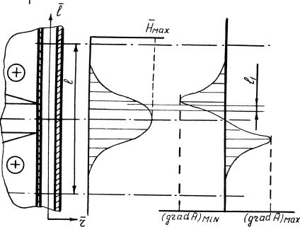
Fig. 2
–
magnetic force:
![]() (6)
(6)
It was assumed that:
– the particles
have a spherical configuration;
– the
e.m.a. is installed striatly vertical and the transverse components were not
taken into account.
In case![]() = 0, values of
= 0, values of ![]() as well as the retention time of
as well as the retention time of
the particle at section l
can be calculated as:
![]() (7)
(7)
In case H ≠ 0 at the e.m.a. section l,with a negative intensity gradient
some ratio of magnetite particles – S will e retained;this will happen
if ![]() islarger then,
islarger then, ![]() ,
, ![]() being negligible.
being negligible.
The limiting diameter of the retained magnetite
particlesand agglomerate can be calculated from the expression
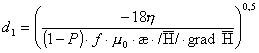 (8)
(8)
-
Hereby at the e.m.a. gap section ![]() (fig2) the local concentration o–f magnetite will increase
resulting in water velocity growth in this suspended layer, according to the
relation;
(fig2) the local concentration o–f magnetite will increase
resulting in water velocity growth in this suspended layer, according to the
relation;
![]() (9)
(9)
This –bransient process shall be completed,
when ![]() , reaches the value:
, reaches the value:
![]() (10)
(10)
Proceeding from this model it is possible to
calculate the retention time ![]() of a certain part of
magnetite – S on the e.m.a. section 1:
of a certain part of
magnetite – S on the e.m.a. section 1:
![]() (11)
(11)
In table 2
calculated values of ![]() on basis of the real parameters of the
used flash evaporator and e.m.a. as function of
on basis of the real parameters of the
used flash evaporator and e.m.a. as function of ![]() and S'at H≠O are presented. The values of
the used parameters are:
and S'at H≠O are presented. The values of
the used parameters are:
![]() = 1,5 m/s; P = 0,5; 1,= 8·10-3
= 1,5 m/s; P = 0,5; 1,= 8·10-3
ρp = 5,2·103k6/m3;
p=103 kg/m3; C =100 p.p.b;
m = 2,75; μ0=1,25·10-6
H/m; f = 0,33; ![]() = 50;
= 50;
n = 5·10-
Pa·S; (![]() ) min = - 7,5 • 1011 A2/m3
) min = - 7,5 • 1011 A2/m3
Table 2
Calculated values of the
parameter TH
|
d. |
d, 10-5
m |
TH (h) |
|
||
|
|
|
|
S = 0,5 |
S = 0,1 |
S = 0,05 |
|
|
|
5 |
4,3 |
21,5 |
42,6 |
|
|
|
6 |
8,9 |
45,7 |
87,4 |
|
|
|
7 |
12,5 |
62,7 |
124,9 |
|
|
|
8 |
15,7 |
78,7 |
157,4 |
The parameter th defines
the beginning of coagulated magnetite particles, entrance from the e.m»a« into
the heat transfer system;
up to
this moment those particles have been for a rather long time retained in a
suspended state in the supersaturated flowo An analogous phenomena (retention
of ferromagnetic compounds) is used in well known electromagnetic filters where
the time th is in accordance with
the operation cycle time. In it's essence the used e.m.a. is a peculiar
electromagnetic filter with a rather small operation cycle time. Understanding
the value and importance of th as
some e.m.a., 'activation"time made it possible to clear up the lack of
coincidence, often noted during operation of e.m.a*
-
An estimation of scale-forming compounds precipitation processes in the
e.m.a. gap at H = 0 and H ^ 0, taking into account equations 3, 7
and 11, shows that;
!• An external magnetic field sharply increases the retention
time of ferromagnetic corrosion products in
the e.m.a. gap with their subsequent coagulation.
2. In a supersaturated on scale – forming
compounds aqueous system retention of coagulated magnetite particles will
promote sorp— tlon on their surface of these scale for^n coEuounds.
5. Leaving the e.m.a., such coagulated and
agglomerated particles farther in the heat-transfer system play the role of
seed crystalls, changing the picture of scale formation.
Bibliography
- E.F.Tebenikhin. Methods
of water treatment for power plants without chemical agents. Moscow,
«Energy», 1977, p.l84
2. O.I.Martynova,
B.T.Gusev, E.A.Leontiev. About the mechanism of magnetic field influence on
aqueous salt solutions. Advances in Physical Sciences, 1969, V. 98. No 1.
3. A.S.Kopylov,
E.F.Tebenikhin, V.F.Ochkov. The use of a magnetic field to reduce
scale-formation when heating high-mineralized water. Transaction of the Moscow
Power Institute, 1976, v. 509, p»55-60.