10
Gas
power cycles
10.1 Cycles of reciprocating internal combustion
engines
As can be seen from its
name, an internal combustion engine is a heat engine in which heat is added to the
working medium by fuel combustion inside the engine. In these engines at the
first stage, the working medium is air or a mixture of air and an easily
inflammable fuel, and at the second stage, the products of combustion of this
liquid or gas fuel (gasoline, kerosene, solar oil, etc.). In gas engines, the
working medium does not undergo very high pressures and its temperatures are
well above the critical temperature, which permits us to consider the working
medium as an ideal gas thereby, significantly simplifying the thermodynamic
analysis of the cycle.
Internal combustion engines
possess two important advantages, compared with other types of heat engines.
First, since the high-temperature heat source, associated with an internal
combustion engine, is located as if inside the engine itself, there is no need
for large heat-transfer surfaces through which heat is transferred from a
high-temperature source to the working medium. This advantage permits compact
designs of internal combustion engines, compared with thermopower plants. The
second advantage of internal combustion engines consists in the following. For
heat engines, in which heat is added to the working medium from an external
high-temperature source, the uppermost cycle temperature of the working medium
is limited by the temperature admissible for structural materials (for example,
an increase in the temperature of steam, used as a working medium in
steam-turbine plants, is limited by the properties of the grades of steel used
to make the components of the steam boiler and turbine; an increase in
temperature is accompanied by a reduction in the ultimate strength of
materials). The uppermost value of the continuously changing temperature of the
working medium, to which heat is added not through the walls of the internal
combustion engine but by the heat released in the volume of the working medium
itself, can considerably exceed this limit. It should also be kept in mind that
the cylinder walls and the head of the engine are positively cooled, permitting
a considerable increase in the temperature range of the cycle, and thereby
increasing its thermal efficiency.
Internal combustion engines
(of the reciprocating type) are used to power automobiles, tractors, small
airplanes, etc.
The main component of any
reciprocating, or piston-type, engine is the cylinder with a piston connected
to an external work consumer by means of a crank gear. The cylinder has two
openings with valves, through one of which the working medium (air or the
fuel-air mixture) is drawn (induced) into the cylinder, and through the other
valve the working medium is exhausted upon completion of the cycle.
Three main cycles of
internal combustion engines are distinguished: the Otto cycle (combustion at V
= const), the Diesel cycle (combustion at p = const), and the
Trinkler cycle (combustion first at V = const and then at p = const).
Let us consider the Otto
cycle (named after the German engineer N. Otto, who developed this cycle in
1876).
The schematic diagram of an
engine operating on the Otto cycle and the indicator diagram of this engine are
shown in Fig. 10.1.
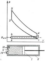
Fig. 10.1
Piston I reciprocates
in cylinder II fitted with an inlet (III) and exhaust (IV) valves. In the process a-I the
piston moves from the left to the right, a rarefaction is created inside the
cylinder, the inlet valve III opens
and the combustible mixture, prepared in a special device, the carburetor, is
injected into the cylinder. In the Otto cycle the fuel mixture consists of air
mixed with a certain amount of vapourized gasoline (or the vapour of another
fuel). After the piston reaches its extreme right position and the process of
filling the cylinder with the fuel mixture terminates and the inlet valve
closes, the piston begins to move in the opposite direction, from right to
left. During this piston stroke the fuel mixture filling the cylinder is compressed
and its pressure rises (process 1-2). After the pressure of the fuel
mixture reaches a certain magnitude, corresponding to point 2 on the
indicator diagram, the fuel mixture is ignited with the aid of spark plug V. Since combustion of the fuel mixture
is instantaneous and the piston has no time to move, the process of combustion
can be assumed to proceed isochorically. Combustion is accompanied by the
release of heat, spent to heat the working medium filling the cylinder. As a
result, its pressure rises to a magnitude corresponding to point 3 on
the indicator diagram. This pressure forces the piston to move again from left
to right and perform work of expansion which is transferred to an external
consumer. After the piston reaches the right dead centre (RDC), a special
device engages to open exhaust valve IV
and the cylinder pressure reduces to a value somewhat exceeding atmospheric
pressure (process 4-5), with a fraction of the gas leaving the cylinder.
The piston then travels again from right to left, ejecting the remaining part
of the waste, or exhaust, gas into the atmosphere[1].
Then, a new cycle
initiates, with suction of a new portion of the fuel mixture, compression of
the mixture, and so on.
Thus, the piston of an internal
combustion engine operation on the Otto cycle accomplishes in the course of the
cycle four strokes: intake, or admission, compression, expansion upon
combustion of the fuel mixture, and exhaust, or ejection, of the combustion
products into the atmosphere.
It is convenient to analyze
the Otto cycle from the thermodynamic viewpoint, considering an ideal cycle
corresponding to the indicator diagram summarized above. Such an ideal Otto
cycle is represented on the p-v diagram, shown in Fig. 10.2, plotted
for unit mass of the working medium.
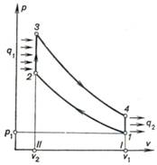
Fig. 10.2
A real cycle of an internal
combustion engine is an open cycle, since the working medium is drawn into the
engine from the outside and is exhausted into the atmosphere upon completion
of the cycle. Thus a new portion of the working medium takes part in each
cycle. Inasmuch as the amount of fuel contained in the fuel mixture and
delivered into the engine cylinder is relatively small compared with the amount
of air, to facilitate the analysis the cycle of an internal combustion engine
can be assumed to be closed. We will also assume that the working medium of the
cycle is air, whose amount in the engine remains constant, and that heat q1 is added to the working
medium from an external high-temperature source isochorically through the
cylinder (processes 2-3) and, correspondingly, that heat q2 is rejected from the
working medium to the low-temperature source following the isochor 4-1. From
the viewpoint of a thermodynamic analysis such a closed cycle is no different
from an open Otto cycle.
Inasmuch as in this cycle
the processes of compression (1-2) and expansion (3-4) proceed in
rather short time intervals, there can be no appreciable heat exchange with the
surroundings, and these processes can be assumed to proceed adiabatically with
good approximation.
Thus, an ideal closed
cycle, thermodynamically equivalent to the Otto cycle, consists of two adiabats
(adiabat of compression 1-2 and adiabat of expansion 3-4) and two
isochors (isochor of heat addition 2-3 and isochor of heat rejection 4-1).
The work performed by the engine per cycle (cycle work output) is depicted
by area 2-3-4-1-2.
Let us determine the
thermal efficiency of the Otto cycle.
The amount of heat q1 added to the working medium in
the isochoric process 2-3 is determined from Eq. (7-6):
![]() (10.1)
(10.1)
where T2 and T3 are the working medium temperatures
before and after the addition of heat, respectively, and cv is the mean heat capacity of the working medium
within the temperature interval considered (if the working medium is assumed to
be an ideal gas with a constant heat capacity, then cv is the constant heat capacity of such a gas).
The amount of heat rejected
from the working medium in the isochoric process 4-1 amounts to
![]() (10.2)
(10.2)
where T4 and T1 are the temperatures of the
working medium before and after the rejection of heat.
It follows that, in
accordance with the general definition
![]()
the thermal efficiency of
the Otto cycle can be expressed as follows
![]() (10.3)
(10.3)
If heat capacity cv is assumed to be constant, the expression (10.3)
takes the following form:
 (10.4)
For an ideal gas undergoing
an adiabatic process the ratio ![]() is determined from relationship (7.60a):
is determined from relationship (7.60a):
![]()
Denote by ε the ratio
of the specific volumes of the working medium before and after compression:
![]() (10.5)
(10.5)
The quantity ε is called the compression
ratio.
Taking Eq. (10.5) into account we can present Eq. (7.60a) in the following
form:
![]() (10.6)
(10.6)
For the adiabats 1-2 and
3-4 we can write Poisson's equation:
![]() (10.7)
(10.7)
and
![]() (10.8)
(10.8)
Dividing Eq. (10.8) by (10.7)
and taking into account that v2 =
v3, and v4 = v1 we obtain:
![]() (10.9)
(10.9)
or
![]() (10.10)
(10.10)
If we take Eqs. (10.6) and
(10.10), Eq. (10.4) for the thermal efficiency of the Otto cycle becomes:
![]() (10.11)
(10.11)
The thermal efficiency of
the Otto cycle is plotted in Fig. 10.3 as a function of the compression ratio
ε for k = 1.35.
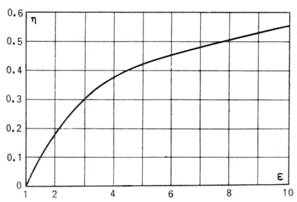
Fig. 10.3
In accordance with Eq.
(10.11), the thermal efficiency of the Otto cycle depends only on the degree of
compression of the working medium in the adiabatic process 1-2; the
higher the compression ratio ε, the higher the thermal efficiency of the
cycle.
The conclusion that
preliminary compression (precompression) of the working medium (gas) results in
a higher thermal efficiency of an engine is rather important, and it will be
shown below that this conclusion is valid for any internal combustion engine.
Speaking
of cycles realized in internal combustion engines, we should mention the engine
created by the French inventor J.
E. Lenoir in 1859. In
this the fuel (illuminating gas) was burned in the combustion chamber at
atmospheric pressure. The thermal efficiency of this engine was rather low
(3-4%).
The
conclusion that precompression of air will permit a considerable increase of
the thermal efficiency of an engine was a great step forward in the development
of the theory of internal combustion engines. It is interesting to note that
the idea of the expediency of compressing the air before delivering it into the
combustion chamber of an internal combustion engine was first advanced by S.
Carnot as early as 1824. The design of an engine based on constant volume of
air compression and combustion was first suggested by A. Beau de Rochas in
1862; later Otto constructed an engine in which this cycle was realized.
Thus, from the viewpoint of
higher thermal efficiency, it is expedient to raise the compression ratio in
every way possible. In practice, however, it proves impossible to operate
engines with very high compression ratios ε, accompanied by an increase in
temperature and pressure, due to the fact that upon reaching a certain
compression ratio spontaneous ignition of the fuel mixture often takes place
before the piston comes into its extreme left position in the cylinder. As a
rule this process involves the appearance of knocking, or detonation, and
destroys the components of an engine. Thus, for conventional carburetor engines
the compression ratio does not exceed twelve. The compression ratio depends on
the quality of the fuel fired, increasing with improved antiknock properties
of the fuel characterized by the octane number.
The heat q1 added to the working
medium in the Otto cycle (see the T-s diagram shown in Fig. 10.4) is
represented on the T-s diagram by the area a-2-3-b-a, and the
heat q2 rejected
from the working medium, by the area 1-2-3-4-1[2].
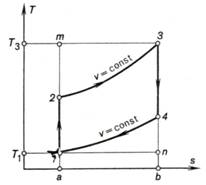
Fig. 10.4
Carburetor engines operated
on the Otto cycle are widely used in practice to power light vehicles, motor trucks,
and airplanes with reciprocating engines.
The compression ratio
ε can be raised if not the fuel mixture but only pure air is
compressed. The fuel is then injected into the engine cylinder after
compression is terminated. The Diesel cycle (named after the German engineer
R. Diesel) is based on exactly this principle. An internal combustion engine
operated on this cycle was constructed by Diesel in 1897. The schematic diagram
of the engine operated on the Diesel cycle and the indicator diagram of this
engine are represented in Fig. 10.5. In the process a-1 atmospheric air
is drawn into the cylinder, and in the process 1-2 this air undergoes
adiabatic compression to pressure p2 (Diesel engines are usually operated with a
compression ratio ε ranging from 15 to 16).
Then the compressed air begins to expand and simultaneously fuel (kerosene or
solar oil) is injected into the cylinder through a special fuel injection
valve. Because of the high temperature of the compressed air the fuel ignites
and burns at a constant pressure, which is ensured by the expansion of the gas
from v2 to v3 at p = const.
The Diesel cycle is, therefore, referred to as the constant-pressure combustion
cycle.
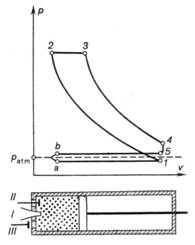
Fig. 10.5
After the process of fuel
injection terminates (point 3), further
expansion of the working medium follows the adiabat 3-4. In the state
corresponding to point 4 the exhaust valve opens, the cylinder pressure
reduces to atmospheric (following the isochor 4-5) and then the gas is
exhausted from the cylinder into the atmosphere (line 5-b). Thus, the
Diesel cycle is a four-stroke cycle.
To facilitate analysis, let
us replace this Diesel cycle with a thermodynamically equivalent ideal closed
cycle, realized with pure air. The p-v diagram of this cycle is shown in
Fig. 10.6. As can be seen from this diagram, the ideal Diesel cycle comprises
two adiabats (the adiabat of compression 1-2
and the adiabat of expansion 3-4), the isobar 2-3 along which the heat q1
is transferred from the high-temperature source, and the isochor 4-1
along which the heat q2 is rejected to the low-temperature
source, or sink.
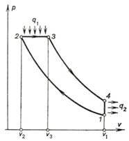
Fig. 10.6
We shall calculate the thermal
efficiency of this cycle (assuming, as before, that the air used as the working
medium in this cycle is an ideal gas with a constant heat capacity).
Let us introduce one more
notation, the degree of preliminary expansion ρ:
![]() (10.12)
(10.12)
From the general expression
for, the thermal efficiency of any cycle,
![]()
taking into account the
fact that in the isochoric process 4-1 [see Eq. (10.2)]
![]()
and in the isobaric process 2-3
![]() (10.13)
(10.13)
we obtain:
![]() (10.14)
(10.14)
or,
taking Eq. (7.55) into account,
 (10.15)
When an ideal gas undergoes
an isobaric process,
![]() (10.16)
(10.16)
For the processes 1-2 and 3-4 the equations of an adiabat give:
![]()
![]()
Allowing for v4 = v1 and p2 =
p3 and dividing Eq. (10.8) by Eq. (10.7), we obtain:
![]() (10.17)
(10.17)
Replacing in Eq. (10.17) p1 and p4 on the isochor v4 = v1, following Clapeyron's
equation and taking into account Eq. (10.12), we obtain:
![]() (10.18)
(10.18)
Substituting Eqs. (10.16) and
(10.18) in Eq. (10.15), we get the following expressions for the thermal
efficiency of the Diesel cycle:
![]() (10.19)
(10.19)
This relationship shows
that the thermal efficiency of the Diesel cycle is the higher the greater the compression
ratio ε (just as in the Otto cycle) and the smaller the quantity ρ.
The thermal efficiency of
the Diesel cycle is plotted in Fig. 10.7 as a function of the compression
ratio ε for various values of the quantity ρ and at k = 1.35.
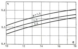
Fig. 10.7
The Diesel cycle is
represented on the T-s diagram in Fig. 10.8. The quantity q1 is represented on the
diagram by the area a-2-3-b-a, the quantity q2 by the area a-1-4-b-a and the work of the cycle lc is represented by the area
1-2-3-4-1.
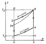
Fig. 10.8
Let us compare the thermal
efficiencies of the Otto and Diesel cycles. These cycles can be compared
assuming for the two cycles either an equal compression ratio ε or the
same highest temperature of the working medium undergoing the cycles (T3).
It is also understood that the initial properties of the working medium at
the initial point of a cycle (p1, v1, T1)
are the same for the two cycles.
If the compression ratio is
assumed to be the same for the two cycles, then it is clear from Eqs. (10.11) and
(10.21) that the thermal efficiency of the Otto cycle exceeds the thermal efficiency of the
Diesel cycle. It is, however, hardly proper to compare the thermal efficiencies
of these cycles at the same compression ratio ε, since, as was already
mentioned above, the advantage of the Diesel cycle consists in its ability to
realize the cycle with higher compression ratios.
A comparison of the thermal
efficiencies of the Otto and Diesel cycles realized at the same highest cycle
temperature (T3) shows that the thermal efficiency of
the Diesel cycle is higher. In particular, this can be seen from the T-s diagram shown in Fig. 10.8; since cp > cv i.e.
![]() , it
follows that on the T-s diagram an isochor runs steeper than an isobar
(in Fig. 10.8 the isochor of the Otto cycle is drawn with a dotted line), indicating
that the area ratio of the Diesel cycle exceeds that of the Otto cycle.
Comparing the two cycles on the condition that the work lc = q1 — q2 is the same for the two
cycles realized at the same maximum
pressure, we can easily see that more heat q2 is involved in the
Otto cycle than in the Diesel cycle and the thermal efficiency is lower. Such a
comparison is more justified and gives reasons to consider the Diesel cycle to
be more efficient than the Otto cycle.
, it
follows that on the T-s diagram an isochor runs steeper than an isobar
(in Fig. 10.8 the isochor of the Otto cycle is drawn with a dotted line), indicating
that the area ratio of the Diesel cycle exceeds that of the Otto cycle.
Comparing the two cycles on the condition that the work lc = q1 — q2 is the same for the two
cycles realized at the same maximum
pressure, we can easily see that more heat q2 is involved in the
Otto cycle than in the Diesel cycle and the thermal efficiency is lower. Such a
comparison is more justified and gives reasons to consider the Diesel cycle to
be more efficient than the Otto cycle.
It should also be noted
that a Diesel engine, requiring no carburation of the fuel fired, can be
operated with a lower grade fuel.
The major shortcomings of
Diesel engines, compared with the Otto engine, consist in the necessity of
spending work to drive the device ensuring atomization of fuel and in the
relatively low speed, due to the lower rate of fuel combustion.
A kind of a hybrid of the
Otto and Diesel cycles is the mixed (or dual) combustion Trinkler[3]
cycle, sometimes also referred to as the Sabatier cycle. Engines
operating on this cycle (Fig. 10.9) have a so-called forechamber open to
the working cylinder through a narrow channel. The p-v diagram for this
cycle is shown in Fig. 10.10. In the working cylinder air is compressed
adiabatically due to the inertia of the flywheel set on the engine shaft; the
air heats in the course of compression to a temperature ensuring ignition of
the liquid fuel delivered into the forechamber (process 1-2). The shape and location of
the forechamber contribute to a better mixing of the fuel and air, resulting in
rapid combustion of a fraction of the fuel in the small volume of the
fore-chamber (process 2-5).
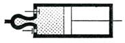
Fig. 10.9
Due to the rise in pressure
in the forechamber, the mixture of the unburned fuel, air, and products of
combustion formed in it is forced into the working cylinder where combustion of
the unburned fuel takes place, accompanied by displacement of the piston from
left to right at an approximately constant pressure (process 5-3). Upon completion of fuel
combustion the products of combustion expand further adiabatically (process 3-4); the exhaust gases are then
expelled from the cylinder (process 4-1).
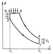
Fig. 10.10
Thus, in a dual combustion
engine heat q1, is first
added along the isochor (q'1),
then following the isobar (q1").
Unlike the Diesel engine a
dual-combustion engine requires no high-pressure compressor to ensure atomization
of the liquid fuel: The liquid fuel introduced into the forechamber at a
comparatively low pressure is sprayed (atomized) by the jet of compressed air
coming from the engine cylinder. In addition, the dual combustion cycle
preserves to some extent the advantages of the Diesel cycle over the Otto
cycle, since a part of the process of fuel combustion proceeds at a constant
pressure.
Let us determine the
thermal efficiency of the dual combustion cycle.
The amount of heat q2 [the heat rejected along
the isochor (4-1)]
present, in the general relation for the thermal efficiency,
![]()
is found, as before, from the relationship (10.2):
![]()
whereas the quantity q1 is the sum of the heat
added in the isochoric process
2-5 (q'1) and
the heat added in the isobaric process 5-3 (q1"), i.e.
![]() (10.20)
(10.20)
It is clear that
![]() (10.21)
(10.21)
and
![]() (10.22)
(10.22)
It follows that the thermal
efficiency of the mixed, or dual, combustion cycle is
![]() (10.23)
(10.23)
or
 (10.24)
For the isochor 4-1 Clapeyron's
equation gives:
![]() (10.25)
(10.25)
The equations for the
adiabats 1-2 and 3-4 can take the form ![]() ,
, ![]()
Dividing Eq. (10.8) by Eq.
(10.7) and taking into account that ![]() , we
obtain:
, we
obtain:
![]() (10.26)
(10.26)
Since p3 = p5
(isobar 5-3), and v2 = v5 (isochor 2-5), the above
relationship can be transformed to
![]() (10.27)
(10.27)
where ![]() is the pressure ratio in the isochoric process of
combustion, and
is the pressure ratio in the isochoric process of
combustion, and ![]() is the degree of preliminary expansion in the
isobaric process of combustion.
is the degree of preliminary expansion in the
isobaric process of combustion.
Accounting for Eq. (10.27),
we obtain from Eq. (10.26):
![]() (10.28)
(10.28)
For the isochor 2-5
![]() (10.29)
(10.29)
and for the isobar 5-3
![]() (10.30)
(10.30)
Finally, in accordance with
Eq. (10.6),
![]()
Taking into account
equations (10.28) to (10.30) and (10.6), we obtain from relationship (10.24):
![]() (10.31)
(10.31)
For ρ = 1 (which corresponds
to a cycle with no isobaric process) Eq. (10.31) turns into Eq. (10.11) for the
thermal efficiency of the Otto cycle, and for λ = 1 (a cycle with
no isochoric process) Eq. (10.31) turns into Eq. (10.19) for the thermal
efficiency of the Diesel cycle.
Comparing the thermal
efficiency of the dual combustion cycle with the thermal efficiencies of the
Otto and Diesel cycles, we see that at the same compression ratio ε
![]() (10.32)
(10.32)
and at equal maximum cycle temperatures (T3)
![]() (10.33)
(10.33)
The above inequalities are
illustrated graphically on the T-s diagram shown in Fig. 10.11. In
particular, relationship (10.33) follows from the fact that in all three cycles
the amount of heat q2, equal to the area a-1-4-b-a,
is the maximum work output in the Diesel cycle (area 1-2b-3-4-1), the mean work output in the dual
combustion cycle (area 1-2-5-3-4-1)
and the minimum work output in the Otto cycle (area 1-2a-3-4-1).
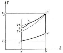
Fig. 10.11
It will also be noted that
in four-stroke engines during the admission and exhaust strokes (ejection of
the combustion products) proceeding at approximately atmospheric pressure the
engine performs uncharacteristic work. Therefore, in up-to-date high-speed
reciprocating engines, for instance, motorcycle engines, the entire working
cycle is realized in two strokes. The admission and exhaust (ejection) strokes
are eliminated, since the working medium enters the cylinder and is exhausted
from it through special openings replacing the intake and exhaust valves and
not closed by the moving piston. Two-stroke engines realize the same cycles as
four-stroke engines.
The results of this
analysis of the effectiveness of the cycles realized in internal combustion
engines hold true only for ideal cycles with no allowance for irreversibility
and for a number of other factors. In real cycles the properties of the working
medium (air, during the first two strokes of the Diesel cycle and of the dual
combustion cycle, or fuel mixture in the Otto cycle; air and products of
combustion during the next strokes) differ from those of an ideal gas with a
constant heat capacity; due to the inevitable friction, the processes of
adiabatic compression and expansion proceed not along an isentrop, but with
rising entropy; the forced cooling of cylinder walls increases even more the
deviation of these processes from isentropic ones. Combustion takes place in
short but nevertheless finite intervals of time during which the piston has
time to displace through a certain distance, so that the condition of the
isochority of the process is not so strictly observed; there are mechanical
losses in the mechanism, too.
The same reasoning pertains
to the exhaust process when the exhaust valve opens.
Therefore, when passing from the ideal thermodynamic
cycles, investigated above, to real cycles, we must introduce the concept of
the relative efficiency of an engine, the magnitude of which is determined by
testing the engine.