10.2 Gas turbine cycles
One of the main drawbacks
inherent in reciprocating internal combustion engines is the need for a crank
gear and flywheel and the inevitable irregularity of crankshaft rotation.
These shortcomings make it impossible to concentrate a high capacity in one
unit, restricting the application of reciprocating engines.
Another type of internal
combustion engine, the gas turbine, is free from this drawback. Possessing a
high thermal efficiency and at the same time possessing all the advantages of a
rotary engine, i.e. the possibility of concentrating large capacities in small
units, the gas turbine has great potential. Currently, the application of gas
turbines in highly efficient power plants is limited chiefly because the insufficient
heat resistance of up-to-date structural materials permits the dependable
operation of gas turbines only at temperatures considerably inferior to those
characteristic of reciprocating internal combustion engines, resulting in a
lower thermal efficiency of the plant. Further progress in making new strong
and heat-resistant materials will make it possible to operate gas turbines at
higher temperatures.
Presently, gas turbines are
used in aviation, marine power plants, railroad transport and are being
gradually introduced into power-generating. Gas turbines are divided into two
main types:
(i) constant-pressure
(combustion) gas turbines (p =
const),
(ii) constant-volume
(combustion) gas turbines (v = const).
Thus, gas turbines are
classified by the method of fuel combustion in the same way as reciprocating
internal combustion engines.
The schematic diagram of a constant-pressure
gas-turbine plant is given in Fig. 10.12. Mounted on a common shaft are gas
turbine 1, compressor 2, fuel pump 3 and power consumer 4
(represented by the symbol of a three-phase a.c. generator). The compressor
draws atmospheric air, compresses it to the pressure required and directs the
compressed air into combustion chamber 5 into which the fuel pump
delivers fuel from tank 9. Liquid and gaseous fuels
are suitable. In gas-fired gas turbines the pump is replaced with a gas
compressor.
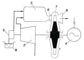
Fig. 10.12
Fuel combustion proceeds in
the combustion chamber at p = const. The products of combustion,
expanding in the nozzles 6 of the gas turbine, hit the turbine blades 7, and produce work on the blades; the
waste gas is then exhausted into the atmosphere through exhaust duct 8. The
pressure of the exhaust gas somewhat exceeds atmospheric pressure.
The ideal cycle of the
gas-turbine plant under consideration is plotted on the p-u diagram in
Fig. 10.13.
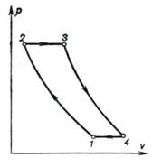
Fig. 10.13
The construction principle
of this ideal cycle does not differ from that of the cycles of reciprocating
engines: the cycle is assumed to be closed, i.e. the amount of the working
medium is constant throughout the cycle. The discharge of the waste gas into the
atmosphere is replaced by an isobaric process with heat rejection to a
low-temperature source; it is assumed that heat q1 is added
to the working medium from an external source, through the walls of the turbine
casing. It is also assumed that the working medium is a gas of constant
composition such as pure air. On the indicator diagram shown in Fig. 10.13
process 1-2 represents the compression of air in the compressor (as was
shown in Sec. 7.9, the process of compression can be adiabatic, isothermal, or
polytropic). Heat is added to the working medium along the isobar 2-3 (this
process corresponds to the combustion of fuel in the combustion chamber). The
working medium (air and combustion products in the real cycle) then expands adiabatically in the turbine
nozzles and transfers work to the turbine wheel (process 3-4). The
isobaric process 4-1 corresponds to the exhaust of the waste gas from
the turbine[1].
Let us determine the
thermal efficiency of the cycle of a constant-pressure combustion gas turbine,
sometimes referred to as the Brayton cycle. Just as before, the working medium
is assumed to be an ideal gas with a constant heat capacity.
The thermal efficiency of
this gas turbine will differ, depending on whether the process of compression
accomplished is isothermal, adiabatic, or polytropic.
Let us consider first the cycle
of a constant-pressure combustion gas-turbine plant with isothermal
compression[2] of
air in the compressor. The T-s diagram of this cycle is depicted in Pig.
10.14.
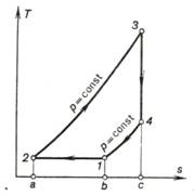
Fig. 10.14
In this case heat will also
be rejected from the working medium to the low-temperature source in the
isobaric process 4-1 (area b-1-4-c-b in Fig. 10.14) and in the
process of isothermal compression 1-2 (area a-2-1-b-a), with the
quantity of heat rejected during the isobaric process 4-1 being
![]() (10.34)
(10.34)
and the quantity of heat rejected during the
isothermal process 1-2 being [in accordance with Eq. (7.22a)]
![]() (10.35)
(10.35)
Thus, the total amount of
heat rejected is
![]() (10.36)
(10.36)
The quantity of heat added
to the working medium in the isobaric process 2-3 is
![]() (10.37)
(10.37)
Substituting these values
of q1 and q2 into the general relation for the
thermal efficiency,
![]()
we obtain:
 (10.38)
Dividing the numerator and
the denominator of the right-hand side of Eq. (10.38) by cpT1 and having in mind
that for an ideal gas
![]()
we
obtain:
 (10.39)
The notation of the degree
of preliminary expansion, p = v3/v2,
introduced in the preceding section, will also be used below.
Let us denote the ratio of
the pressure at the end of expansion to the pressure at the beginning of the
process by
![]() (10.40)
(10.40)
This quantity is called the
pressure ratio of the process of compression. It is clear that in the
isobaric process 2-3
![]() (10.41)
(10.41)
and that in the adiabatic process 3-4
 (10.42)
or, which is the same
(since p3
= p2 and p4 = p1),
 (10.43)
Substituting Eqs. (10.41)
and (10.43) into Eq. (10.39) and taking into account that
![]()
we obtain the expression
for the thermal efficiency of a gas turbine operated with constant-pressure
combustion (isothermal compression of
air):
 (10.44)
The dependence of the
thermal efficiency η on ρ for various values of β (at k =
1.35), described by Eq. (10.44), is presented graphically in Fig. 10.15.
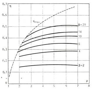
Fig. 10.15
Equation (10.44) can be
used to find the maximum value of the thermal efficiency for different degrees
of preliminary expansion ρ. For this purpose take the first derivative of
the thermal efficiency with respect to the pressure ratio β at ρ = const. After doing the required transformations
we obtain
![]() (10.45)
(10.45)
Equating
this expression with zero, we obtain the following condition for the maximum
thermal efficiency:
![]() (10.46)
(10.46)
It will be noted that at ![]() the
cycle is represented graphically by a triangular diagram.
the
cycle is represented graphically by a triangular diagram.
Replacing in Eq. (10.44) β
with its value from Eq. (10.46), we obtain the maximum thermal efficiency at a
given ρ:
![]() (10.47)
(10.47)
On the graph shown in Fig.
10.15 the line of maximum efficiencies is represented by the dotted line[3].
Consider now the cycle
of a constant-pressure combustion gas turbine (p
= const) for the adiabatic compression of air in the
compressor of the gas-turbine plant. The T-s diagram of this cycle is
shown in Fig. 10.16.
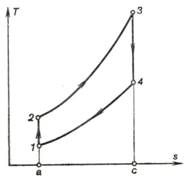
Fig. 10.16
In this case
 (10.48)
It follows from (10.48)
that the thermal efficiency of this cycle is determined from the expression
![]() (10.49)
(10.49)
or
 (10.50)
The temperature ratios
present in Eq. (10.50) are easily expressed in terms of ρ and β.
Indeed, for the adiabatic process 1-2
 (10.51)
On the other hand, from the fact that p3 = p2 and p4 = p1 it follows that

Thus, for this cycle,
![]() (10.52)
(10.52)
and
![]()
or
![]() (10.53)
(10.53)
The thermal efficiency of
this cycle is plotted in Fig. 10.17 as
a function of β at k = 1.35.
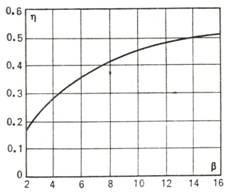
Fig. 10.17
A comparison of the
effectiveness of cycles realized in constant-pressure combustion gas turbines
for isothermal and adiabatic compression, conducted with equal amounts of added
heat q1, maximum pressures
p3 and
maximum cycle temperatures T3
(inasmuch as in the two cases the initial cycle pressure p1 is equal to
atmospheric, the condition of equality of pressures p3 corresponds to the condition of equality of the pressure ratios
β), shows the
thermal efficiency of the cycle with adiabatic compression to exceed that of
the cycle with isothermal compression:
![]() (10.54)
(10.54)
This conclusion can be easily deduced by plotting
the cycles being analyzed on a common
T-s diagram shown in Fig. 10.18. In accordance with the
conditions of comparison previously assumed, the pressure in the process of
heat addition (2-3) and the pressure during the exhaust process (4-1'-1)
are the same in both cycles, as well as the values of q1 and T3. It is clear from the T-s
diagram that the work output of the cycle with adiabatic compression (area 1-2-3-4-1)
is greater than the work output of the cycle with isothermal compression
(area 2-3-4-1'-2). With the same value of q1 it leads to the inequality
(10.54).
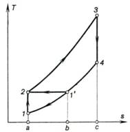
Fig.
10.18
It is clear that when a constant-pressure
combustion gas turbine is operated with polytropic air compression and an
exponent 1 < n <
k, its thermal efficiency will fall between ![]() and
and ![]() .
.
The thermal efficiency of a
constant-pressure combustion gas turbine (p
= const) can be increased by practising heat regeneration.
The concept of heat
regeneration was introduced in Sec. 3.6
when considering reversible cycles. It was shown that regeneration
raises the thermal efficiency of a cycle since the area ratio increases. The
schematic diagram of a gas-turbine plant incorporating a constant-pressure
combustion gas turbine with heat regeneration is shown in Fig. 10.19.
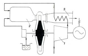
Fig. 10.19
A gas-turbine plant with
heat regeneration differs from one without heat regeneration in that the
compressor 1 does not discharge compressed air directly into the
combustion chamber 2 but first passes it through the heat exchanger 3
where it is heated by the exhaust gases. Correspondingly, before being
rejected into the atmosphere, the exhaust gases pass through the heat exchanger
where they are cooled heating the compressed air. Thus, a certain fraction of
the heat, previously lost with the exhaust gases, is now utilized in the
turbine operated on the regeneration cycle.
The regenerative cycle of a
constant-pressure combustion gas-turbine plant is shown in Fig. 10.20.
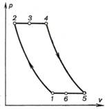
Fig. 10.20
This cycle involves either
isothermal or adiabatic air compression in the compressor 1-2, process 2-3
ensuring isobaric heating of the air in the regenerator (heat exchanger),
isobaric process 3-4 corresponding to heat addition in the combustion
chamber upon fuel combustion, process 4-5 of adiabatic expansion of
gases in the turbine, isobaric cooling of the exhaust gas in the heat exchanger
in process 5-6, and finally, the hypothetical isobaric process 6-1, closing
the cycle.
The completeness of heat
generation is usually determined by the degree of regeneration, or the regeneration
fraction
![]()
i.e. by the ratio of the heat which was actually
utilized in the process of regeneration (process 2-3) to the heat available,
corresponding to the possible temperature difference, T5 — T2.
The quantity of heat
transferred to the compressed air in the regenerator should naturally be equal
to the amount of heat lost by the exhaust gases in the regenerator, i.e.
![]() (10.55)
(10.55)
Thus, taking into account
the previously assumed condition that the heat capacity of air does not change
with temperature, we get:
![]() (10.56)
(10.56)
Let us denote by γ = T3/T2
the ratio of the air temperature at the heat-exchanger outlet, T3, to the air temperature at the
heat-exchanger inlet, T2. In
the limiting case of complete regeneration it is clear that the temperature T3 = T5 and, consequently, the
degree of regeneration σ = 1. For this case
there is a limiting value γmax:
![]() (10.57)
(10.57)
Let us now consider the regenerative
cycle of a constant-pressure gas turbine with isothermal air compression. Figure
10.21 shows this cycle on a T-s diagram. In the presence of
regeneration, the heat rejected along section 5-6 of isobar p2 = const is added to the
working medium along section 2-3 of isobar px = const
(consequently, on the T-s diagram shown in Fig. 10.21 area c-6-5-d-c is
equal to area a-2-3-b-a); in
Fig. 10.21 this process is indicated by an arrow.
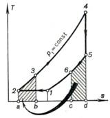
Fig. 10.21
The heat added in this
cycle is
![]() (10.58)
(10.58)
the heat rejected is
![]() (10.59)
(10.59)
The amount of heat rejected
with the exhaust gases can be determined taking into account Eq. (10.55):
![]() (10.60)
(10.60)
Then,
![]() (10.61)
(10.61)
The thermal efficiency can
now be determined as
 (10.62)
Dividing the numerator and
denominator of Eq. (10.62) by
cpT1 and
allowing for T1 = T2, we obtain:
 . (10.63)
Denoting the ratios ![]() and
and ![]() we now
determine the values of
the temperature ratios in Eq. (10.63), taking into account that
we now
determine the values of
the temperature ratios in Eq. (10.63), taking into account that
![]() (10.64)
(10.64)
Then,
 (10.65)
![]() (10.66)
(10.66)
Replacing in Eq. (10.63) for the thermal efficiency
the pressure and temperature ratios with their notations β, ρ and
γ, we get:
 (10.67)
It follows that the greater
γ is (γ characterizes the degree of
regeneration), the higher is the thermal efficiency of a constant-pressure
combustion gas-turbine plant.
With a maximum degree of
regeneration, σ = 1
and, consequently, γmax = T5/T2 = T5/T1. All the heat
available in the exhaust gases is then utilized to heat the compressed air.
Such regeneration is referred to as complete. It is clear that this case is
only of theoretical importance, since at a zero temperature difference between
the exhaust gases and air, which would have taken place in the event of
complete regeneration, no heat transfer is possible in the regenerator, the
heat exchanger. Figure 10.22 shows
the cycle with complete regeneration on a T-s diagram. It is clear that
area a-2-3-b-a equals area c-1-5-d-c. In this case at T3 = T5 the
degree of preliminary expansion will be:
 (10.68)
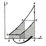
Fig. 10.22
Substituting (10.68) into Eq. (10.67), we obtain:
 (10.69)
It follows that the thermal
efficiency of a constant-pressure combustion gas-turbine plant operating with
complete regeneration does not explicitly depend on ρ. Since the limited
degree of regeneration of the given cycle is expressed in terms of γmax
= T5/T1 the thermal efficiency of
this cycle can be directly determined by the temperature at the
end of expansion, T5, i.e.
 (10.70)
The higher the temperature T5, the higher the thermal efficiency of the cycle.
Equation (10.70) shows the necessity of raising the temperature T5 at the
end of expansion which unfortunately is hampered due to the comparatively low
mechanical strength of the materials of gas-turbine blades at high
temperatures.
The thermal efficiency of
the cycle of the given gas-turbine plant operating with complete regeneration
is plotted as a function of the pressure ratio β at different values of T5 in Fig. 10.23.
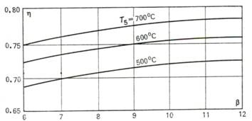
Fig. 10.23
It can be easily shown that
regeneration increases the thermal efficiency of a cycle, as is clear, for
instance, from the T-s diagram shown in Fig. 10.22. In fact, the work
output per cycle of a gas-turbine plant, lc, will be
the same both with and without regeneration (this work is represented by area 1-2-3-4-5-6-1),
whereas the heat q1
added in the cycle will be represented by area a-2-3-4-5-d-a for the
cycle without regeneration, and by area b-3-4-5-d-b, for the cycle with
regeneration.
Taking into account the
fact that area b-3-4-5-d-b is smaller than area a-2-3-4-5-d-a, it
follows from the equation for thermal efficiency presented in the form
![]()
that the thermal efficiency of the regenerative
cycle is higher than that of the cycle without heat regeneration.
Now let us determine the
thermal efficiency of a constant-pressure combustion gas-turbine plant
operated on a regenerative cycle with adiabatic air compression.
Fig. 10.24 shows the cycle on a T-s diagram.
The heat transferred from the exhaust gases in the regenerator is represented by
area c-6-5-d-c and the heat added to the compressed air passing through
the heat exchanger, by area a-2-3-b-a.
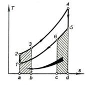
Fig.
10.24
The added heat is
![]() (10.71)
(10.71)
the rejected heat is
![]() (10.72)
(10.72)
but since
![]()
we have:
![]() (10.73)
(10.73)
The thermal efficiency of
the cycle will then have the following form:
![]() (10.74)
(10.74)
Dividing the numerator and
denominator of Eq. (10.74) by cpT1, we
obtain:
 (10.75)
Let us express the
temperature ratios in Eq. (10.75) in terms of ρ, β and γ. The equations of the
adiabats give the following for the processes 1-2 and 4-5:
and
i.e.
![]()
or
![]()
Thus,
![]()
![]()
![]()
Therefore
 (10.76)
The maximum possible degree
of regeneration, or regeneration fraction occurs at T3 = T5, i.e. at γmax
= T5/T2. A cycle with a maximum degree of regeneration is
shown on a T-s diagram in Fig. 10.25. Just as on the T-s diagram
in Fig. 10.24, the heat rejected from the exhaust gas in the regenerator is
represented by area c-6-5-d-c,
and the heat added to the compressed air passing through the
regenerator by area a-2-3-b-a.
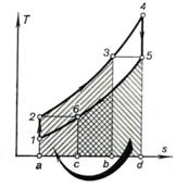
Fig. 10.25
In this case we have
![]()
and
![]()
Then
 (10.77)
Formula (10.77) can be transformed to show
the dependence of the maximum thermal efficiency on gas temperature at the end
of expansion, or T5.
As is known, with a maximum
degree of regeneration
![]()
thus
![]() (10.78)
(10.78)
Thus, the thermal
efficiency of a constant-pressure gas-turbine plant operating with maximum
regeneration[4]
and adiabatic compression depends only on the temperature of the gas at the end
of adiabatic expansion, T5,
an important characteristic determining the design of a turbine (the
initial gas temperature T1
is usually assumed constant). The maximum thermal efficiency is plotted in
Fig. 10.26 as a function of final temperature T5, with T1 = 300 oC.
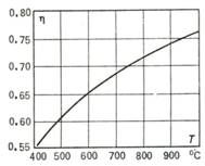
Fig. 10.26
Let us now compare two
gas-turbine cycles, with isothermal compression and complete regeneration and
with adiabatic compression and maximum regeneration, both cycles being realized
at different initial pressures and temperatures and at the same maximum
pressures and temperatures (with the temperatures at the end of expansion being
the same for the two cycles, as shown in Fig. 10.27).
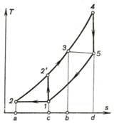
Fig. 10.27
The thermal efficiency of
the cycle with isothermal compression and complete heat regeneration
![]()
and the thermal efficiency
of the cycle with adiabatic compression and maximum heat regeneration
![]()
Since in this case equal
amounts of heat q1
(area b-3-4-d-b) are added to the working medium from an outside
source, and the work outputs of the two cycles are different, with the cycle,
involving isothermal compression producing more work (area 1-2-4-5-1 is
greater than area 1-2'-4-5-1), the thermal efficiency of the cycle with
isothermal compression and complete regeneration is always greater than the
thermal efficiency of the cycle with adiabatic compression and maximum
regeneration.
Thus, with a maximum
possible heat regeneration, isothermal compression is more expedient than
adiabatic.
Along with the
constant-pressure combustion gas turbine, constant-volume combustion gas
turbines can also be constructed. The schematic diagram of such a
gas-turbine plant is given in Fig. 10.28, and Fig. 10.29 shows the cycle of
such a plant on a p-v diagram. Compressor 2, sharing a common shaft with turbine 1 proper,
compresses atmospheric air to the pressure required (process 1-2). Air can be compressed both
isothermally and adiabatically. A fuel pump or compressor 3 delivers
liquid or gaseous fuel and the compressed air into combustion chamber 4. Sometimes the fuel and air are not
delivered into the combustion chamber in separate streams, but as a
combustible mixture (fuel-air mixture preliminarily prepared in a carburetor).
With the valves closed the fuel is usually ignited in the combustion chamber
from spark plug 8. Fuel
combustion (process 2-3) proceeds
at a constant volume. After fuel combustion is terminated the exhaust valve
opens and the products of combustion pass into nozzle 5 of the turbine
where they expand adiabatically (process 3-4) to atmospheric pressure. The gases leaving the nozzles
flow onto blades 6 of the turbine, perform work and are discharged into
the atmosphere through the turbine exhaust duct 7. The useful work produced by the plant is transferred to
energy (power) consumer 9. The
cycle is closed by a hypothetical isobaric process 4-1.
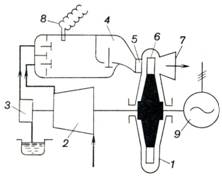
Fig. 10.28
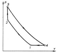
Fig. 10.29
Notwithstanding their
somewhat higher thermal efficiency, constant-volume combustion gas-turbine
plants are less widespread than constant-pressure combustion gas turbines. This
is usually explained by the lower absolute brake thermal efficiency of the
constant-volume combustion gas turbine compared with the absolute efficiency of
the constant-pressure combustion gas-turbine plant, in spite of its higher
thermal efficiency. The latter is mainly due to the uneconomical performance of
the turbine traced to the fact that the properties of the gas flowing into the
turbine vary with time. In addition, the design of
constant-volume combustion gas turbines is far more complicated than that of
gas turbines in which combustion proceeds at a constant pressure, p = const.
Both the reciprocating
internal-combustion engines and the gas-turbine plants, whose cycles were
investigated above, operate on an open cycle and are referred to as open-cycle
machines. In the cycles of the internal combustion turbines considered, the
compressor draws air from the atmosphere, and the exhaust gases are discharged
into the atmosphere from the turbine outlet (or from the regenerator outlet in
gas-turbine plants operating on the regenerative cycle). In this way, in these
plants each new cycle is realized with a fresh portion of the working medium.
As was already mentioned, these cycles were hypothetically plotted and
investigated on p-v and T-s diagrams as closed cycles.
It is possible, however, to
realize an actually closed cycle, possessing in a number of cases certain
advantages over the open cycle. The schematic diagram of a constant-pressure
gas turbine plant operated on a closed cycle is illustrated in Fig. 10.30.
Compressor 1 compresses the working medium to the pressure required and
forces the compressed working medium to flow into regenerator (heat-exchanger) 2
where it is heated at p = const by the hot exhaust gases leaving the
turbine. The heated working medium then flows from the regenerator into heat
exchanger 3 where heat is added from an external source. The heat
exchanger is basically similar to a steam boiler in which gas is heated,
instead of water and steam. Heat is added in the heater by the fuel delivered
by fuel pump 4 (if liquid fuel is fired) and burned in the combustion
chamber. The air required for fuel combustion is delivered by fan 5, and is
preheated in heater 3 by the heat contained in the exhaust gases. The
working medium, heated in heater 3 at p = const, passes into
turbine 6 where it expands and produces work. The exhaust gases are
directed from the turbine into the regenerator in which a fraction of their
heat is transferred to the compressed gas coming from the compressor.
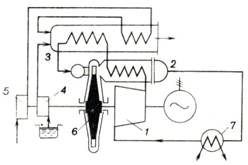
Fig. 10.30
From the regenerator the
waste gases are directed into cooler 7 where they are cooled to the
lowest cycle temperature at p = const. Water is usually used as a
coolant. From the cooler the working medium is sent again into the compressor.
Thus, the same portion of the working medium is continuously engaged in
producing work.
From the point of view of
thermodynamics the operating cycle of this gas-turbine plant is similar to the
regenerative constant-pressure combustion cycle previously analyzed. Therefore
all the formulas for the thermal efficiency of a regenerative constant-pressure
combustion cycle derived above are applicable to the closed cycle. We shall
examine the advantages and drawbacks of the closed cycle, compared with an open
cycle. Since a constant amount of the working medium is involved in the
operation of the closed-cycle gas turbine, not only air and combustion products
but any gas can be used as a working medium. Let us consider the advantage of
replacing air with another working medium.
The formulas for the
thermal efficiency of a cycle derived above with heat addition at
p = const and heat regeneration present the thermal efficiency
of the cycle as a function of not only β, ρ and γ but,
under otherwise identical conditions, of the type of the working medium.
Indeed, apart from β, ρ and γ, all expressions for the thermal efficiency contain the
adiabatic exponent k which depends chiefly on the atomicity of the gas
involved[5].
This indicates the effect
of the properties of the working medium used in the closed cycle on its thermal
efficiency.
An analysis of the Eqs.
(10.67) and (10.76) for the thermal efficiency of this cycle shows that with
the same β, ρ and γ an increase in the adiabatic exponent
leads to a higher cycle efficiency. On the other hand, it is clear that when a
gas with a greater adiabatic exponent is used at the same value of the thermal
efficiency and the same ρ and γ,
the cycle can be realized with a smaller pressure ratio.
For this reason, since it
permits the use of a working medium with a maximum adiabatic exponent, the
closed cycle has definite advantages. Such working fluids can be primarily
monatomic gases, helium and argon (it will be recalled that for an ideal
monatomic gas k = 1.67, whereas for air we assume an exponent k = 1.35).
On the other hand, the
closed cycle permits operation with cycle pressures most advantageous
technically and economically. If the lowest pressure in an open-cycle gas
turbine is atmospheric pressure, then in the closed cycle realized with the
same pressure ratio the initial cycle pressure can be considerably higher than
atmospheric pressure. This permits operation at higher pressures, which leads
to a considerable reduction in the volumes of the gases flowing through the
components of a gas turbine, smaller heat exchange surfaces are required and
the task of creating high-power gas-turbine plants is greatly facilitated.
To raise the thermal
efficiency of a gas-turbine plant it is expedient to introduce multistage
combustion and multistage cooling of the compressed working medium. The T-s diagram
of such a cycle with a great number of stages is shown in Fig. 10.31. Such
gas-turbine plants are operated as open-cycle installations with a rather high
efficiency.
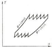
Fig. 10.31
In conclusion we shall
again emphasize that our analysis of the effectiveness of the cycles of
gas-turbine plants was based on the assumption that these cycles are reversible
and that the working medium is an ideal gas whose heat capacity is independent
of temperature. In considering actual gas-turbine plants and reciprocating
internal-combustion engines, cycles should be analyzed taking into account the
losses due to irreversibility, in particular by introducing the concept of the
relative internal efficiencies of a plant.