10.3 Reaction-engine cycles
A reaction engine is a device in which the chemical energy of fuel is
converted into the kinetic energy of the jet propulsion of a working medium
(gas) expanding in the nozzles. This jet creates thrust because of the reactive,
or back action, of the working medium, flowing from the engine backwards
relative to aircraft motion.
If we denote by Ggas the mass of gas flowing
from the exit nozzle of a reaction engine in some time interval ![]() , and use wgas
to denote the velocity of this gas relative to the flying vehicle
(jet-propelled aircraft or rocket) and F to denote the thrust of the reaction engine, then
in accordance with Newton's second law,
, and use wgas
to denote the velocity of this gas relative to the flying vehicle
(jet-propelled aircraft or rocket) and F to denote the thrust of the reaction engine, then
in accordance with Newton's second law,
![]() (10.79)
(10.79)
we obtain for the moving vehicle (taking into
account that the velocity with which the gas flows from the nozzle changes from
a relatively low velocity in the combustion chamber to wgas at the nozzle exit, i.e. ![]() ):
):
![]() (10.80)
(10.80)
or, introducing the notation ggas = Ggas/![]() (the rate of
gas flow),
(the rate of
gas flow),
![]() (10.81)
(10.81)
Reaction engines are
divided into two main categories, rocket engines and jet engines.
Rockets carry both fuel and
an oxidizer required to ensure fuel combustion (liquid oxygen, ozone, hydrogen
peroxide, nitric acid, etc.). Unlike rocket engines, jet engines carry only
fuel, and atmospheric air is used as an oxidizer. Hence, jet engines are only
suitable for operation in the Earth's atmosphere, whereas rocket engines are
capable of service both in the atmosphere and in space.
Let us first consider the
cycles of jet engines. Air-breathing engines are divided into turbojet
and compressorless engines according to the principle of operation.
The schematic diagram of a turbojet
is shown in Fig. 10.32. In this type of engine the liquid fuel, delivered
from the fuel tanks, burns in the combustion chamber 1. The products of
combustion, upon expansion in the nozzle 2, are then discharged into the
surroundings. Air oxygen is the oxidizer for fuel combustion. The thermal
efficiency of this engine is increased by introducing precompressed air. This
air, drawn from the atmosphere through diffuser 3, is compressed in an
axial or centrifugal compressor 4 from which it is discharged into the
combustion chamber. The compressor is driven from a special gas turbine 5 which
is run by a portion of the products of combustion as they pass through it; the
products of combustion then expand in the propelling nozzle.
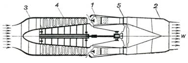
Fig. 10.32
It follows that the cycle
of a turbojet engine is realized as follows (p-v diagram in Fig. 10.33).
Air is compressed in the turbocompressor[1] from
atmospheric pressure p1
to pressure p2 along
adiabat 1-2. Then the heat released upon fuel combustion, q1, is added to the working medium, this process proceeding
under a constant pressure (isobar 2-3). The working medium (compressed air + products of
combustion) expands first in the gas turbine, and then in the propelling (jet)
nozzle 3 of the engine along adiabat 3-4 (from point 3 to
point b doing work in the gas turbine, and from point b to point 4 accelerating the flow in the
nozzle). The cycle is closed by isobar 4-1 at atmospheric pressure.
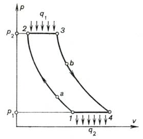
Fig. 10.33
We see that the cycle of a
turbojet engine does not differ from the cycle of a gas-turbine plant where
combustion proceeds at p = const (see Sec. 10.2). Hence, the
relationships previously derived are applicable to the turbojet cycle. At the
present time turbojet engines are the basic type of engine for high-speed
aircraft.
We now turn to the compressorless
jet engines. Here there is no compressor, as the name implies, and compression
of air is due to the conversion of the kinetic energy of the atmospheric air
moving backwards relative to the aircraft, known as the ram effect.
Compressorless jet engines
are divided into two groups: the ramjet and the pulsejet.
The schematic layout of a ramjet
is shown in Fig. 10.34. There is no compressor or turbine in this engine.
Atmospheric air is compressed in diffuser 1 from atmospheric pressure p1 to p2 and flows into
combustion chamber 2 into which liquid fuel is injected. Combustion
proceeds at a practically constant pressure (p2 = const). The products of combustion,
which are at a high temperature, discharge from the propelling nozzle 3.
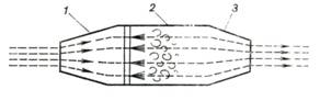
Fig. 10.34
Thus, the cycle of a ramjet
(shown on the p-v diagram in Fig. 10.35) consists of an adiabat
representing compression of atmospheric air in the diffuser (process 1-2), an isobar showing the
process of fuel combustion (process 2-3), an adiabat of air expansion in the propelling nozzle
(process 3-4), and
the cycle closing isobar representing cooling of the products of combustion at
atmospheric pressure (process 4-1).
The cycle of a ramjet is thermodynamically similar to that of a
constant-pressure combustion gas turbine and also to the
cycle of a turbojet. In accordance with Eq. (10.53), the thermal efficiency of
this cycle will be the higher the greater the pressure ratio
β = p2/p1
(i.e. the higher the speed of the aircraft with the ramjet), which
determines the dynamic pressure (head) of the stream of air, turning, as the
air is decelerated in the diffuser, into static pressure. The thermal
efficiency of a ramjet, consequently, increases with aircraft speed.
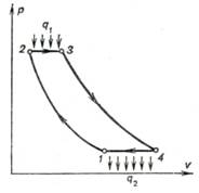
Fig. 10.35
The dependence of the
thermal efficiency of a ramjet cycle on aircraft speed (or, on the velocity of
air relative to the aircraft) can be derived as follows.
Equation (10.53) for the
thermal efficiency of a constant-pressure combustion gas engine (adiabatic air
compression),
![]()
and Eq. (10.51) for adiabatic air compression,

yield that for this cycle
![]() (10.82)
(10.82)
where T1 is the air temperature before compression, and T2 the air temperature
at the end of adiabatic compression.
If we denote the velocity
of air relative to the aircraft (i.e. aircraft velocity) by w1 and the velocity of air flowing into
the combustion chamber by w2, then,
in accordance with the equation derived in Chapter 8, Eq. (8.8), we find that
![]()
where i1 and i2 are the enthalpies of
air before adiabatic compression (i.e. at the inlet of the ramjet diffuser) and
after adiabatic compression (at the diffuser exit, i.e. at the inlet of the
combustion chamber of the ramjet).
Assuming, as before, air to
be an ideal gas with a constant heat capacity, for which
![]() (10.83)
(10.83)
we obtain from Eq. (8.8):
![]() (10.84)
(10.84)
Thus,
 (10.85)
Substituting the above
expression into Eq. (10.82), we obtain the following relation for the thermal efficiency
of a ramjet cycle:
 (10.86)
Ignoring the velocity in
the combustion chamber ![]() , we get
, we get
 (10.87)
The dependence of the
thermal efficiency of a ramjet engine on flight speed, calculated from Eq.
(10.87), is represented graphically in Fig. 10.36.
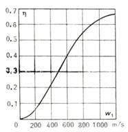
Fig. 10.36
It will be noted that from
Eqs. (10.51) and (10.85) it follows that the dependence of the pressure ratio β
= p2/p1 on
flight speed is determined from the relationship
 (10.88)
Ramjets intended for
subsonic and supersonic speeds should naturally be constructed differently. The
schematic diagram of the ramjet, shown in Fig. 10.34, corresponds to subsonic
speeds. It will be recalled that, as it was shown in Sec. 8.4, a subsonic
stream is decelerated in a diverging nozzle, and the flow is accelerated in a
converging nozzle; this kind of nozzle and diffuser are illustrated in Fig.
10.34. A ramjet for supersonic speeds is shown schematically in Fig. 10.37. To
be suitable for such flight conditions, the diffuser must have a converging
section in which the supersonic flow is decelerated to sonic velocity; further
deceleration of the flow then takes place in the diverging subsonic diffuser.
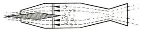
Fig. 10.37
It ought to be mentioned,
however, that, as is known from gas dynamics, the deceleration of a supersonic
flow in a converging duct is accompanied by a number of shock waves inside the
duct, which cause important losses in flow energy, a considerable deviation of
the compression curve from an isentrop and a drop in the pressure ratio. In
order to avoid this, diffusers are fitted with a sharp cone facing the flow
which ensures a gas-dynamical rearrangement of flow from supersonic to subsonic
upstream from the diffuser inlet. Thus, there is no need to fit a converging
section (cone) in front of the diffuser. It is clear that the nozzle is made in
the shape of a supersonic Laval nozzle.
Under subsonic conditions
(take-off and landing) the diverging part of the Laval nozzle and diffuser cone
are idle and serve no purpose; the engine acts as a subsonic plant whose
schematic diagram is shown in Fig. 10.34.
With a flying speed equal
to zero (aircraft take-off) the pressure ratio ensured by a ramjet is one, its
thermal efficiency is zero, and the engine will fail to perform. Ramjet-powered
aircraft are, therefore, fitted with special launching boosters to impart an
initial speed.
These peculiarities of
ramjets and their simple construction, small weight and size make this type of
engine ideal for aeroplanes intended for high supersonic speeds.
The pulsejet whose
performance cycle is shown in Fig. 10.38 on a p-v diagram, is fitted
with a special valve-type device ensuring isolation of the combustion chamber
from the diffuser and nozzle, so that the process of combustion proceeds at a
constant volume. Periodic action characterizes this engine and gives it its
name, the pulsejet. The cycle of a pulsejet is similar to the cycle of the
constant-volume combustion gas turbine, previously studied.
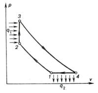
Fig. 10.38
As was shown in the
preceding section, for the same pressure ratios and the same temperatures at
the end of the process of expansion and with adiabatic air compression, the
thermal efficiency of a constant-volume combustion cycle is higher than that
of a constant-pressure combustion cycle.
Because of their intricate
construction, the pulsejet have not yet found wide application.
Let us now examine the
cycles of rocket engines.
Rocket
engines are divided into chemical
rocket engines and nuclear rocket engines.
Chemical
rocket engines are divided, in turn, into
two main groups: solid propellant rocket engines and liquid propellant rocket
engines. In a solid propellant rocket engine, the solid fuel (usually
powders of various kinds), containing both combustible substances and an
oxidizer, takes fire when the rocket is being launched and burns out gradually,
forming gaseous products of combustion which discharge from the nozzle. The
schematic diagram of a solid propellant rocket engine is illustrated in Fig.
10.39, showing combustion chamber 1, solid propellant 2 and nozzle 3.
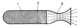
Fig. 10.39
An ideal cycle of a solid
propellant rocket engine is shown on the p-v diagram in Fig. 10.40. When
the engine is started, the pressure of the gaseous products of solid propellant
combustion increases instantaneously from atmospheric pressure p1 to some pressure p2. In different types of
engines, the magnitude of the pressure p2 may reach tens and even hundreds of atmospheres;
the pressure rises at so high a rate that this process may be considered as
isochoric (line 1-2).
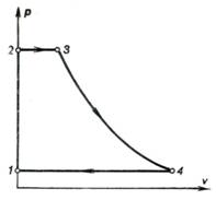
Fig. 10.40
It may be assumed that heat
is added to the products of combustion isobarically (line 2-3). The gaseous products of
combustion then expand adiabatically in the nozzle (line 3-4). The cycle is closed by
isobar 4-1 representing the cooling of the products of combustion in the
surrounding medium. In the combustion chamber, the density of the solid
propellant products of combustion is so high compared with that of the gases
leaving the nozzle that in Fig. 10.40 isochor 1-2 is depicted coinciding
with the vertical axis.
Due to their simple design
and convenient handling in operation, solid propellant rocket engines find an
ever growing application in rocketry.
A schematic diagram of a liquid
propellant rocket engine is presented in Fig. 10.41. The liquid propellant
and the oxidizer are delivered into combustion chamber 1 from
propellant tank 2 and oxidant tank 3 with the aid of pumps 4 and
5. Combustion proceeds at a practically constant pressure p2. The gaseous products of combustion flow through and
discharge from the nozzle into the surroundings.
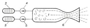
Fig. 10.41
The ideal cycle of a liquid
propellant rocket engine is plotted on the p-v diagram shown in Fig.
10.42.
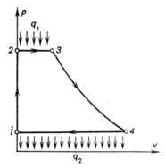
Fig. 10.42
The liquid propellant and
oxidizer (or oxidant) are delivered into the combustion chamber at a pressure p2. Therefore, in a liquid propellant
rocket engine, not a gaseous working medium is compressed, as in a solid
propellant engine, but the individual liquid components of this working medium.
Inasmuch as liquid can be considered virtually incompressible, the compression
of the components of the combustible mixture can be assumed to be isochoric.
Since the density of liquid is much greater than that of the combustion products,
in Fig. 10.42 the isochor 1-2 is plotted as practically coinciding with
the vertical axis. The isobar 2-3 corresponds to the process of heat
addition in the combustion chamber, and adiabat 3-4 represents expansion
in the propelling nozzle. Isobar 4-1 (surroundings pressure) closes the
cycle.
Thus, in principle, the
cycle of a liquid propellant rocket engine is similar to the cycle of a solid
propellant rocket engine.
The thermal efficiency of
the ideal cycle of a liquid propellant rocket engine can be calculated as
follows.
The amount of heat q1 added during the
isobaric process 2-3 is
![]() (10.89)
(10.89)
It should be emphasized
here that, as above, we consider the products of combustion to be an ideal gas
with a constant heat capacity; the amount of heat q1 however, can not be calculated from formula (10.13),
![]()
since the components of the
combustible mixture enters the combustion chamber at a temperature T2 in the liquid state, then evaporate and react
chemically. Thus, on the isobar 2-3 the working medium changes phase; therefore the
amount of heat q1 should be calculated with the aid of the more
general Eq. (10.89), instead of
formula (10.13), to account for any transformation of the substance of this
isobar.
The quantity q2 can be presented in
the form
![]() (10.90)
(10.90)
The general expression for
the thermal efficiency of the cycle,
![]()
taking
into account Eqs. (10.89) and (10.90), takes the following form:
![]() (10.91)
(10.91)
or, which is the same,
![]() (10.92)
(10.92)
The difference in
enthalpies (i2 – i1) is equivalent to the work
expended by pumps 4 and 5 (Fig. 10.41) to raise the pressure of
the liquid components of the combustible mixture during the isochoric process 1-2.[2]
Inasmuch as the
specific volumes of the liquid fuel (propellant) and oxidant are rather small,
the work expended to ensure their compression is negligible compared with the
amount of heat released upon combustion of the liquid propellant. The quantity
(i2 – i1) present in Eq. (10.92) can, therefore, be ignored.
With this in mind, Eq. (10.92) gives the following expression for the thermal
efficiency of the cycle of a liquid propellant rocket engine:
![]() (10.93)
(10.93)
Inasmuch as the difference
in enthalpies (i3 – i4) converts into the kinetic
energy of the products of combustion as they discharge from the nozzle, in
accordance with Eq. (8.8), ignoring the speed of the products of combustion at
the nozzle inlet, we can write
![]() (10.94)
(10.94)
where w is the
velocity with which the products of combustion leave the nozzle of a liquid
propellant engine.
Taking into account
relationship (10.94), Eq. (10.93) can be given the following form:
![]() (10.95)
(10.95)
Liquid-propellant rocket
engines find wide application in rocketry and very often in aeronautical
engineering.
Let us now consider the
cycles of nuclear rocket engines[3].
A possible design of a nuclear
rocket engine is shown schematically in Fig. 10.43. The liquid working
medium, contained in tank 1, is
forced to flow by pump 2 through the core of nuclear reactor 3. In
the nuclear reactor, heat is added to the working medium at a constant
pressure. From the reactor the already gaseous working medium flows into nozzle
4 in which it expands and then discharges into the surroundings. It is
clear that the cycle of a nuclear rocket engine is thermodynamically identical
to the cycle of a liquid propellant rocket engine. Consequently, the thermal
efficiency of the cycle realized in a nuclear rocket engine, just as that of a
liquid propellant rocket engine, is determined by Eq. (10.95).
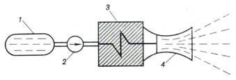
Fig.
10.43
Another possible design of
a nuclear rocket engine is represented schematically in Fig. 10.44. The liquid
working medium, containing the nuclear fuel (uranium-235 or plutonium) in the
form of a suspension or of another mixture, is delivered from tanks 1, fitted with special devices that
prevent a chain reaction, into "combustion" chamber 2, where the mass of the nuclear fuel
exceeds the critical mass and a chain reaction begins. The heat released during
the nuclear reaction heats the working medium, which then expands in nozzle 3
and discharges into the surrounding medium. The cycle of this nuclear
rocket engine is thermodynamically similar to the preceding one.
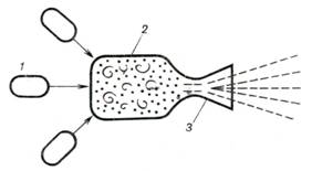
Fig. 10.44
It should be noted that as
distinct from jet engines and rocket engines with a chemical propellant, the
working medium of nuclear jet engines is not a product of fuel combustion. This
means that for a nuclear rocket engine the working medium can be chosen on the
basis of maximum thermodynamic expediency.
From Eq. (8.29) for the
velocity of flow of an ideal gas through a nozzle[4],
we obtain for the case of
flow into an evacuated space (the pressure in outer space can be considered
virtually zero), i.e. for p2
= 0[5] we have:
![]() (10.96)
(10.96)
or, which is the same,
![]() (10.97)
(10.97)
Since the quantity is
constant, it follows from relationship (10.97) that maximum velocities of flow
through a nozzle are ensured when gases with a small molecular weight μ are used. From this point of view
the most advantageous working medium for a nuclear-powered, or nuclear, rocket
is hydrogen H2 (μ = 2), which at the high temperatures in the
"combustion" chamber of the nuclear reactor dissociates into atomic
hydrogen (μ = 1).
Besides hydrogen, helium,
water vapour (steam) and hydrogen compounds of light elements are possible
working media for nuclear rocket engines.
We must note that although
the thrust of nuclear rocket engines is small compared with the thrust of
liquid (or solid) propellant rocket engines, a nuclear engine is capable of
operating for a considerably longer time (several orders of magnitude longer)
than a rocket engine firing a chemical (liquid or solid) propellant. Nuclear
rockets, therefore, are the most suitable type of engine for manned
interplanetary spaceflights. It appears that a spaceship should be launched
from the Earth with the aid of liquid or solid propellant engines, with a
nuclear rocket engine used for flying in space outside the Earth's gravity.