11.3 Rankine cycle analysis allowing for irreversible losses
Let us consider an actual Rankine cycle (one with
irreversible losses). The purpose of this analysis is to find the component elements
of a steam power plant in which the major irreversible losses occur and, with
real examples, to estimate the order of magnitude of these irreversible losses.
For example, let us analyze
the above Rankine cycle realized for the following initial steam conditions: p1 =16 670 kPa (170
kgf/cm2), T1 = 550 °C and p2 = 4.0 kPa (0.04 kgf/cm2).
The actual cycle of a steam
power plant will be analyzed with the aid of the three methods described in Chapter
9: efficiency, entropy calculation of power losses, and exergy analysis. First,
let us investigate the irreversible losses in its real Rankine cycle, using
the method of efficiencies.
In the first place we
should mention the irreversible losses suffered as the steam flows through the
turbine blading and nozzles, which are due to the inevitable friction in the
boundary layer between the blades and steam and to other hydrodynamic
phenomena.
As has already been
mentioned, the process of adiabatic friction-resisted flow proceeds with an
increase in entropy. The irreversible process of frictional adiabatic expansion
was already shown on i-s and T-s diagrams in Fig. 8.12. When the
steam at the turbine exhaust end is wet, the temperature at the end of expansion
will be the same both in the reversible (T2) and irreversible (T2r) processes, since the process of expansion proceeds in both
cases to the same pressure p2,
and in the two-phase region (wet steam) the isobar coincides with the isotherm.
This can also be seen from Fig. 11.15 representing an actual process of steam
expansion in a turbine on i-s and
T-s diagrams.
If the process of steam expansion in the turbine
were reversible (absence of frictional and other losses), the entire heat drop
would have been converted into kinetic energy, and consequently into turbine
work, and in this case:  But
due to the presence of irreversible losses a
smaller amount of work is produced by the turbine in the real process of steam
expansion:
But
due to the presence of irreversible losses a
smaller amount of work is produced by the turbine in the real process of steam
expansion:
 (11.11)
In
accordance with Eq. 8.56, i2r
is always greater than i2
and, consequently,
 (11.12)
The difference  area 1-2-2d-II-I (Fig. 11.15). In this case the
internal relative efficiency of the steam turbine will be determined as
follows:
area 1-2-2d-II-I (Fig. 11.15). In this case the
internal relative efficiency of the steam turbine will be determined as
follows:
 (11.13)
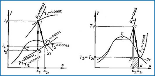
Fig.
11.15
The internal relative
efficiency of up-to-date high-power steam turbines  falls within 0.85 to 0.90.
By analogy, in accordance with
Eq. (11.6) the work expended to drive the pump in the case of no irreversible
losses is equal to:

and for the real process in the presence of
irreversible losses

the enthalpy i5r
is always greater than i5 and,
consequently,

In fact, as was mentioned in Sec. 9.3, the work
transferred to the pump from an external source will always be larger in the
presence of irreversible losses than the work which would be expended to
compress the water in the absence of such losses.
The real adiabatic process,
proceeding in a pump, is compared with a reversible process on the i-s and
T-s diagrams shown in Fig. 11.16. In accordance with (9.13), the
internal relative efficiency of the pump is determined in the following way:
 (11.14)
The value for  usually falls within 0.85
to 0.90, i.e. it is approximately equal to the internal relative efficiency of
the turbine,
usually falls within 0.85
to 0.90, i.e. it is approximately equal to the internal relative efficiency of
the turbine, 
Calculating the losses in
the cycle of a steam power plant, due to the irreversibility of processes, the
losses in the pump are usually ignored: inasmuch
as in the process 3-5 the
enthalpy of water increases slightly compared with the heat drop through the
turbine (process 1-2), the increase in water
entropy resulting from the irreversibility of the process of compression in
the pump,  , is
negligible compared with the increase in entropy due to irreversibility in the
turbine,
, is
negligible compared with the increase in entropy due to irreversibility in the
turbine,  , and
in other components of the plant.
, and
in other components of the plant.
As was shown above, the work
performed in the reversible Rankine cycle in the absence of irreversible losses
is determined from Eq. (11.7):

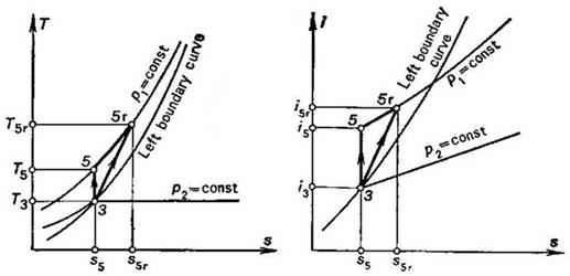
Fig.
11.16
or, which is the same,

By analogy, the work done in the real Rankine cycle
will be
 (11.15)
or, which is the same,
 (11.15a)
Thus, taking into account Eqs. (11.13) and (11.14), it follows that
 (11.16)
Equation (11.16) yields the following expression
for the internal relative efficiency of the turbine-pump set:
 (11.17)
As was shown in the preceding example, for the
Rankine cycle with p1 =16 670 kPa (170 kgf/cm2), T1 = 550 °C and p2 = 4.0 kPa (0.04 kgf/cm2), we have i1
= 3438 kJ/kg (821.2 kcal/kg), i2
= 1945 kJ/kg
(464.5 kcal/kg), i3
= 120 kJ/kg
(28.7 kcal/kg), i5 = 137 kJ/kg (32.7 kcal/kg) and,
consequently,  = 1493 kJ/kg (356.7 kcal/kg) and
  = 17 kJ/kg (4.0 kcal/kg). Assuming
  and
and  , we
find that Eqs. (11.13) and (11.14) give:
, we
find that Eqs. (11.13) and (11.14) give:
 = 1269
kJ/kg (303.2 kcal/kg) and i2r
= 2169 kJ/kg (518 kcal/kg),
= 1269
kJ/kg (303.2 kcal/kg) and i2r
= 2169 kJ/kg (518 kcal/kg),
 = 18
kJ/kg (4.4 kcal/kg) and i5r = 139 kJ/kg (33.1
kcal/kg).
= 18
kJ/kg (4.4 kcal/kg) and i5r = 139 kJ/kg (33.1
kcal/kg).
Hence,
 kJ/kg (53.5 kcal/kg) and
  kJ/kg (0.4 kcal/kg).
The magnitude of  is calculated by Eq.
(11.17):
is calculated by Eq.
(11.17):

Thus, we are not surprised to find that the
relative internal efficiency  is virtually equal to that of the turbine,
  . As was already mentioned
[see Eq. (9.18)], this can be traced to the small amount of work done by the
pump compared with turbine work. Therefore, it will be considered below that
. As was already mentioned
[see Eq. (9.18)], this can be traced to the small amount of work done by the
pump compared with turbine work. Therefore, it will be considered below that
 (11.18)
The internal absolute efficiency of the cycle is

For this cycle turbine
efficiency was shown in the preceding section to be 0.46, hence  , i.e.
39 % of the heat transferred to the working medium in the cycle is converted
into work.
, i.e.
39 % of the heat transferred to the working medium in the cycle is converted
into work.
A fraction of that work is
lost due to mechanical losses in various components of the turbine (friction
in radial and thrust bearings). Also it is expended to drive the oil pump
(delivering machine oil to turbine rubbing parts) and to actuate the turbine
control system. The magnitude of these work expenditures is characterized by
the mechanical efficiency of the turbine,  ,
which is the ratio of the mechanical work transferred
by the turbine to the coupled electric generator (denote this work by
,
which is the ratio of the mechanical work transferred
by the turbine to the coupled electric generator (denote this work by  ) to the work done by the steam as it expands in the
turbine (the already known quantity
) to the work done by the steam as it expands in the
turbine (the already known quantity  ):
):
 (11.19)
If we now determine the
absolute brake thermal efficiency of the turbine plant as
 (11.20)
(the work done by the pump is ignored), it is clear
form Eq. (11.20) that
 (11.21)
Taking into account Eqs.
(11.20) and (9.2), we find that
 (11.22)
This relationship can take
the following form:

Inasmuch as

(here and below i5r is assumed to be smaller than i5), taking into account Eqs. (11.25), (11.27) and (11.30),
we obtain:
 (11.32)
or, which is the same,
 (11.33)
This equation is a special case of Eq. (9.20) derived in Chapter 9.
Assuming in this example that  = 0.99 and
  = 0.91, we obtain with the aid of Eq. (11.32):

Thus, this heat power plant, operated on the
Rankine cycle, converts 33% of the heat released upon fuel combustion in the boiler
unit furnace into work transferred to an external consumer. In other words, of
the amount of heat q' = 3663 kJ/kg (874.8
kcal/kg) released upon fuel combustion (per 1 kg of steam generated), 1207
kJ/kg (283.3 kcal/kg) is converted into electric power.
It will be recalled that in the above example the
thermal efficiency of the reversible cycle is 0.46 (and the thermal efficiency
of the reversible Carnot cycle,  = 0.63). But due to the
presence of irreversible losses the efficiency of the real heat power plant,
operated on this cycle, reduces to
= 0.63). But due to the
presence of irreversible losses the efficiency of the real heat power plant,
operated on this cycle, reduces to  = 0.33 (i.e. by more than 26% in relation to
  ). Thus, rather great
losses are suffered in actual heat power plants due to irreversibility.
). Thus, rather great
losses are suffered in actual heat power plants due to irreversibility.
Let us return to Eq. (11.25). Allowing for Eq.
(11.2), we find that Eq. (11.25) yields:

One kg of steam, whose enthalpy is i1 at the turbine exit, does
work  in the plant which is transferred to an
external consumer.
in the plant which is transferred to an
external consumer.
But if D kg of steam flow into the
turbine per hour, the amount of electric power generated per hour (or, in other
words, the electric power of the generator) will be
 (11.34)
It follows from Eq. (11.30) that to generate 1 kg
of steam at the necessary initial conditions, the following amount of heat
should be released in the boiler furnace:

Correspondingly, to generate D kg of steam
per hour, the following amount of heat should be released in the furnace:
 (11.35)
If we denote the calorific,
or heating, value of fuel (i.e. the amount of fuel released when 1 kg of fuel
is burned) by  then the quantity of fuel B which
must be burned per hour in the boiler furnace to release heat Q' will
be
then the quantity of fuel B which
must be burned per hour in the boiler furnace to release heat Q' will
be
 (11.36)
Taking Eq. (11.35) into
account, we find that the hourly consumption of fuel in the boiler of the steam
power plant is
 (11.37)
Replacing in Eq. (11.37)
the product  using Eq. (11.34), we
obtain:
using Eq. (11.34), we
obtain:
 (11.38)
or, allowing for Eq. (11.32),
 (11.39)
This relationship gives the
amount of fuel B
required to ensure the generation of a given electric power (N)
with the aid of a steam-turbine power plant operating with an
efficiency  ; the required fuel consumption
will naturally depend on the calorific value of fuel, i.e. on its quality.
; the required fuel consumption
will naturally depend on the calorific value of fuel, i.e. on its quality.
The electric power
(capacity) of a heat power plant is usually expressed in killowatts (kW). If N is
expressed in kW, and  in kJ/kg,
then to determine the amount of fuel B in kg/h, relation (11.39) should
be presented in the following form:
in kJ/kg,
then to determine the amount of fuel B in kg/h, relation (11.39) should
be presented in the following form:
 (11.39a)
but if N is expressed in kW and the
calorific value  in kcal/kg, Eq. (11.39) takes
the following form:
in kcal/kg, Eq. (11.39) takes
the following form:
 (11.39b)
inasmuch as 1 kW ^ 860
kcal/h. A more accurate value is given in Table 2.1.
In practice, the performance of an electric station
is often estimated by the specific fuel consumption which is the quantity of
fuel burned to generate 1 kW-h of electric power:
 (11.40)
The higher the efficiency of a thermopower plant,
the smaller the specific fuel consumption.
Knowing the values of turbine efficiency and the
efficiencies of all main component elements of the plant, we can determine the
loss of heat in each of these elements.
The heat released upon fuel combustion, q', will be assumed as 100%. The
losses of heat in the boiler will amount to
 (11.41)
In this example  = 0.91. Consequently, the ratio
  amounts to 9 %. The losses of heat in
pipelines (steam mains) are
amounts to 9 %. The losses of heat in
pipelines (steam mains) are
 (11.42)
Allowing for Eq. (11.28), we obtain:
 (11.43)
inasmuch as
 (11.44)
we have
 (11.45)
Here = 0.99 and  = 1 %. Consequently, as the boiler and pipeline
losses amount to 10% of the quantity of heat released upon fuel combustion, the
amount of heat
= 1 %. Consequently, as the boiler and pipeline
losses amount to 10% of the quantity of heat released upon fuel combustion, the
amount of heat
q1 =  =
=  constitutes 90% of q'.
Further, since in the
general form the internal absolute efficiency of the cycle is expressed by the
relationship
 (11.46)
the amount of heat  transferred
to the low-temperature source during the cycle (i.e. the heat rejected in the
condenser) is
transferred
to the low-temperature source during the cycle (i.e. the heat rejected in the
condenser) is
 (11.47)
or, which is the same,
 (11.48)
consequently,
 (11.49)
Thus, taking into account
formulas (11.30) and (11.2), we get:
 (11.50)
In our example  = 0.39 and, consequently,
  = 55%.
Therefore, the heat lost in the boiler and
pipelines and transferred to the low-temperature source amounts to 9 + 1 + 55 =
65% of the heat released in the boiler furnace upon fuel combustion. The
remaining 35% of that heat is converted into turbine work. From the equation

we obtain:
 (11.51)
or, which is the same,
 (11.52)
It is clear that the
mechanical losses in the turbine amount to
 (11.53)
thus, taking Eq. (11.52) into account, we get:
 (11.54)
The mechanical efficiency was assumed  = 0.97; for this value of it follows from Eq. (11.54) that
  = 1%.
= 1%.
It follows from Eq. (11.19) that the mechanical
work transferred to the turbine-generator shaft is

or, allowing for Eq. (11.52),
 (11.55)
(in this example  = 34%).
Finally, the electric and mechanical losses
in the generator are
 (11.56)
Substituting into this expression the value of  from Eq. (11.55), we get:
 (11.57)
Since in this example the efficiency of the
generator is 0.98, we have  = 1 %. The work transferred
to the external consumer (into the network) is equal to
= 1 %. The work transferred
to the external consumer (into the network) is equal to
 (11.24a)
Thus, taking equation (11.55) into account, we get:
 (11.58)
or, which is the same,
 (11.59)
The heat flows of this thermopower plant are
illustrated in Fig. 11.17 and plotted in accordance with the results of the
above analysis. This diagram, showing the sources of the main heat losses,
illustrates well the ideas outlined in this section.
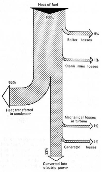
Fig.
11.17
Let us analyze the same Rankine cycle with the aid
of the entropy calculation method of the availability loss.
As has been shown in Sec. 9.4, the loss of
availability of a system  is equal to the sum of the
losses
is equal to the sum of the
losses  in each of the n elements of the system
(plant) considered:
in each of the n elements of the system
(plant) considered:

It will be recalled that
the loss of availability in an element of the system is determined by the
relationship
 (11.60)
where T0 is the temperature of surroundings,
and  the
increase in entropy in this system element due to the irreversible processes
proceeding in it.
the
increase in entropy in this system element due to the irreversible processes
proceeding in it.
It should be emphasized
that in Secs. 11.2 and 11.3 the brake thermal efficiency of the steam turbine
plant was compared with the thermal efficiency of a "standard"
cycle, i.e. of the reversible Carnot cycle,  ,
realized in the same temperature interval as the
Rankine cycle (T1=
550 °C, T2 = 28.6 °C in this example).
Strictly speaking, it is not quite right to compare this cycle with the Carnot
cycle; here the high-temperature source is represented by the furnace gases at
a temperature Th.t. equal to about 2000 °C, and the
low-temperature source is the water used as a coolant in the condenser. The
temperature of this water is equal to that of the surroundings, Tl.t, and ranges from zero to 20 °C.
Therefore, in principle, the effectiveness of real
cycles should be compared with the thermal efficiency of a reversible Carnot
cycle realized for this temperature interval (Th.t. to
Tl.t).
If the upper temperature of the Carnot cycle (550 °C in this example) is
lower than that of the high-temperature source and the cycle's lower
temperature is higher than that of the low-temperature source, such a Carnot
cycle will be irreversible. However, since in actual steam power plants the
upper temperature of the working medium is always far below the temperature in
the boiler furnace,
in practice real cycles are compared with reversible Carnot cycles, realized in
the interval of temperatures characteristic of the working medium used in this
real cycle. In other words, the real cycle is compared with a Carnot cycle
which is reversible internally and irreversible externally (see Sec. 9.4). But
from the position of the analysis of the availability of a system, as was shown
in Sec. 9.4, the actual cycle should be compared with an externally reversible
Carnot cycle.
,
realized in the same temperature interval as the
Rankine cycle (T1=
550 °C, T2 = 28.6 °C in this example).
Strictly speaking, it is not quite right to compare this cycle with the Carnot
cycle; here the high-temperature source is represented by the furnace gases at
a temperature Th.t. equal to about 2000 °C, and the
low-temperature source is the water used as a coolant in the condenser. The
temperature of this water is equal to that of the surroundings, Tl.t, and ranges from zero to 20 °C.
Therefore, in principle, the effectiveness of real
cycles should be compared with the thermal efficiency of a reversible Carnot
cycle realized for this temperature interval (Th.t. to
Tl.t).
If the upper temperature of the Carnot cycle (550 °C in this example) is
lower than that of the high-temperature source and the cycle's lower
temperature is higher than that of the low-temperature source, such a Carnot
cycle will be irreversible. However, since in actual steam power plants the
upper temperature of the working medium is always far below the temperature in
the boiler furnace,
in practice real cycles are compared with reversible Carnot cycles, realized in
the interval of temperatures characteristic of the working medium used in this
real cycle. In other words, the real cycle is compared with a Carnot cycle
which is reversible internally and irreversible externally (see Sec. 9.4). But
from the position of the analysis of the availability of a system, as was shown
in Sec. 9.4, the actual cycle should be compared with an externally reversible
Carnot cycle.
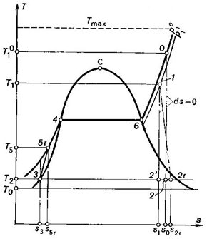
Fig.
11.18
Fig. 11.18 shows the real
Rankine cycle on a T-s diagram,
in which 1-2r represents
the process of adiabatic steam expansion in the turbine, taking into account the
irreversible frictional losses; 2r-3 is
the isobaric-isothermal process of heat rejection in the condenser; 3-5r the adiabatic process in the feed
pump, taking into account the irreversible frictional losses; 5r-4-6-0 the isobaric process
of heat addition to the cooling water (5r-4), vapour-water mixture (4-6) and
to superheated steam (6-0) in the boiler; the curve 0-1 represents in an exaggerating way
the drop in steam temperature from  to T1 and the pressure drop from
  to p1,
taking place on the way from the boiler to the turbine because of losses in
the steam main. Because of those losses, when heat is rejected, the entropy of
the working medium and the theoretical and actual work of the cycle diminish,
as can be seen from Fig. 11.18.
to p1,
taking place on the way from the boiler to the turbine because of losses in
the steam main. Because of those losses, when heat is rejected, the entropy of
the working medium and the theoretical and actual work of the cycle diminish,
as can be seen from Fig. 11.18.
The dotted isothermal line,
shown on this diagram, corresponds to the temperatures of the high-temperature
source (temperature in the furnace, Tmax= Tf).
The temperature of the
surroundings is assumed to be equal to the temperature of the cooling water, T0. For
this thermopower plant it is assumed that Tf = 2000 °C and T0 = 10 °C.
Let us calculate the loss
of availability in each component of the power plant, per kilogram of the
working medium.
(I) Boiler unit. As before, the quantity
of heat released upon fuel combustion in the boiler furnace is denoted by q'. The
loss of availability in the boiler has two causes: first, a fraction of the
heat q' is lost, and
second, the heat realized in the boiler furnace upon fuel combustion is added
to the working medium at a considerable difference between the temperature of
the gases Tf and the
working medium (it changes in the process of heat addition from T5r to  ).
).
The loss of availability
due to the loss of heat is calculated in the following way. The magnitude of
the heat loss is calculated from Eq. (11.41):

On the basis of the considerations outlined in Sec.
3.6 it is clear that the increase in system entropy, due to the transfer of
heat  from the furnace at a temperature Tf to the surroundings at a
temperature T0, will amount to
from the furnace at a temperature Tf to the surroundings at a
temperature T0, will amount to
 (11.61)
It follows, in accordance with Eqs. (11.41) and
(11.60), that the loss of system availability due to the irreversibility of the
process will amount to
 (11.62)
In this example,

Let us now determine the loss of system
availability resulting from the irreversibility of the process in which the
heat released in the furnace is added to the working medium.
The quantity of heat added to the working medium as
it is being heated in the boiler is equal, according to equation (11.29), to

As this amount of heat is
transferred to the working medium, the entropy of the high-temperature source
(burning fuel) diminishes by
 (11.63)
(as a first approximation the temperature in the
boiler furnace, Tf, is assumed constant), and the entropy of the
working medium will increase bv
 (11.64)
(see Fig. 11.18). Inasmuch as in the process of
heating the temperature of the working medium increases from T5r to , the change in the entropy of the working medium  cannot be calculated with the aid of relationships
of the type
cannot be calculated with the aid of relationships
of the type

which is valid provided in the process of heat
addition the temperature of the working medium remains constant. The quantity ,
however, can be determined with the aid of the Steam Tables, T-s or i-s
diagrams plotted on the basis of known values of  , and T5r.
The entire change in system
entropy due to the irreversibility of the process of heat addition to the
working medium will be
 (11.65)
and, accordingly, the loss
of system availability during this process is
 (11.66)
For the example considered,
let us find  and
and  , with
the aid of Steam Tables. We find the magnitude of knowing the enthalpy of
steam in this state
, with
the aid of Steam Tables. We find the magnitude of knowing the enthalpy of
steam in this state  = 3472 kJ/kg (829.2
kcal/kg) and steam pressure p1 =
16 670 kPa (170 kgf/cm2); from the Steam Tables we find that
= 3472 kJ/kg (829.2
kcal/kg) and steam pressure p1 =
16 670 kPa (170 kgf/cm2); from the Steam Tables we find that
= 6.5029 kJ/(kg-K) = 1.5532 kcal/(kg-K)
(correspondingly, = 562 °C). Knowing
i5r = 139 kJ/kg (33.1
kcal/kg), we find for the same pressure
s5r = 0.4241 kJ/(kg-K) = 0.1013
kcal/(kg-K) [T5r = 29.5 °C].
In accordance with Eq.
(11.60), we obtain:

The entire loss of availability, due to the
irreversibility of the processes developing in the boiler, is
 (11.67)
For this cycle

(II) Steam main. In accordance with Eq.
(11.45), the losses of heat in the steam main amount to

Because of these heat losses, the temperature of
the steam in the steam main drops from  at the entrance to T1 at the exit.
Inasmuch as the difference between and T1 is not very great, it may
be assumed that the temperature of the steam flowing through the steam main is

The increase in system entropy due to the transfer
of heat in the steam main from the steam at a temperature  to the surroundings at a temperature T0 amounts to
 (11.68)
It follows that the loss of
system availability due to this process amounts to:
 (11.69)
In this example = 562 °C and T1 = 550 °C. Consequently, = 556 °C, and from Eq.
(11.69) it follows that

(III) Turbine-generator unit. In the course of frictional adiabatic expansion of
steam in a turbine entropy increases. Let us calculate the increase in steam
entropy due to the irreversibility of the process of steam expansion in the
turbine,  In accordance with
Eq. (8.69),
If the exhaust steam (at the turbine exit) is wet
(Fig. 11.18), then T2 = T2r and Eq. (8.69) yields:
 (11.70)
It follows from Eq. (11.70)
that
 (11.71)
Further, it is easy to obtain from Eq.
(11.13) that
 (11.72)
From the above relation, we get from Eq. (11.71):
 (11.73)
or, which is the same,
 (11.73a)
From this it follows that
 (11.74)
As can be seen from Eqs. (11.72) and (11.74), the
loss of work due to friction appearing as the steam flows through the turbine
is greater than the loss of availability  This is explained by the
fact that the work lost on account of friction, equal to i2r — i2, turns
into heat and is removed from the turbine at a temperature of T2 >
T0. It is clear that, in principle, a fraction of that heat
can again be converted into work in a cycle realized in the temperature
interval from T2 to
T0. But
if T2 = T0, the loss of work is equal to the loss
of availability.
This is explained by the
fact that the work lost on account of friction, equal to i2r — i2, turns
into heat and is removed from the turbine at a temperature of T2 >
T0. It is clear that, in principle, a fraction of that heat
can again be converted into work in a cycle realized in the temperature
interval from T2 to
T0. But
if T2 = T0, the loss of work is equal to the loss
of availability.
In this cycle  ,
,  and
and
T2 = 28.6 °C. Substituting these values into Eq.
(11.74), we obtain:

Account should also be
taken of the losses of availability due to mechanical losses in the turbine
and electrical losses in the electric generator (let us denote these losses by  and
and  respectively).
It follows from Eq. (11.19)
that the mechanical losses in the turbine,
 (11.75)
are determined in the following manner:
 (11.76)
Thus, taking Eqs. (11.11) into account, we get:
 (11.77)
or
 (11.78)
By analogy, the mechanical
and electrical losses in the generator,
 (11.79)
are determined in accordance with Eq. (11.56):
 .
.
Thus, taking into account
Eqs. (11.11) and (11.19), we get:
 (11.80)
or
 (11.81)
The losses  and
and  are transferred in the form
of heat to component elements of the turbine and generator. This heat is
transferred at a constant temperature, since the plant is in steady-state
operation. Assuming, as a first approximation, that this temperature is close
to that of the surroundings, T0, we find that the increase
in system entropy, due to losses in the turbine and generator, can be
determined from the formulas
are transferred in the form
of heat to component elements of the turbine and generator. This heat is
transferred at a constant temperature, since the plant is in steady-state
operation. Assuming, as a first approximation, that this temperature is close
to that of the surroundings, T0, we find that the increase
in system entropy, due to losses in the turbine and generator, can be
determined from the formulas
 (11.82)
and
 (11.83)
Thus, for the quantities  and
and  we obtain:
 (11.84)
and
 (11.85)
As was already mentioned, for T2 = T0 the loss of system
availability is equal to the loss of work.
In this example  =
0.97,
=
0.97,  = 0.98 and, consequently,
  = 38 kJ/kg (9.1 kcal/kg) and
  = 25
kJ/kg (5.9 kcal/kg).
= 25
kJ/kg (5.9 kcal/kg).
The total loss of
availability traced to the irreversibility of the processes proceeding in the
turbine-generator unit can be presented in the following manner:
 (11.86)
in this example
 kJ/kg
(65.2 kcal/kg).
kJ/kg
(65.2 kcal/kg).
(IV) Condenser. In accordance with Eq.
(11.48), the heat removed from the steam undergoing an isobaric-isothermal
process in the condenser amounts to

Assuming the rate of flow of cooling water through
the condenser to be so high that its temperature T0 remains practically
constant in the condenser, we obtain:
 (11.87)
and, accordingly,
 (11.88)
In our example  = 2169 kJ/kg (518.0 kcal/kg),
  = 120 kJ/kg (28.7 kcal/kg) and
 kJ/kg (30.2 kcal/kg).
(V) Feed pump. The increase in entropy due
to the irreversibility of the adiabatic process in the feed pump is calculated
in the following way. From Eq. (11.14),

we find that the
supplementary increase in entropy because of the heat released due to friction  amounts to
 (11.89)
Since the temperatures T5r and T5 (Fig. 11.16) differ little-from each
other (in this example
T5 = 29.0 °C and T5r = 29.5 °C), we can write
 (11.90)
where
It follows from Eq. (11.90) that the increase in the entropy of water in the pump,
∆ ,
amounts to
,
amounts to
 (11.91)
Thus, taking Eq. (11.89) into account, we get:
 (11.92)
or, which is the same,
 (11.92a)
where  the theoretical work of the
pump.
the theoretical work of the
pump.
It follows that
 (11.93)
In this example  =
29.2 °C, and so
=
29.2 °C, and so
 kJ/kg (0.4 kcal/kg).
The values of the losses of
availability (power losses) in individual elements of this cycle are given in
Table 11.1.
Table 11.1 Losses of availability in a steam power plant
|
Plant elements
|
Reasons for loss
|
Availability loss 
|
Availability loss factor

|
|
kJ/kg
|
kcal/kg
|
|
Boiler unit
|
Boiler heat losses
|
288
|
68.9
|
8.9
|
|
Irreversible heat exchange
|
1305
|
311.7
|
40.5
|
|
Steam main
|
Heat losses
|
22
|
5.3
|
0.7
|
|
Turbine-generator
|
Irreversible process of steam expansion in turbine
|
210
|
50.2
|
6.5
|
|
Mechanical losses in turbine
|
38
|
9.1
|
1.2
|
|
Mechanical and electrical losses in generator
|
25
|
5.9
|
0.8
|
|
Condenser
|
Irreversible heat exchange
|
126
|
30.2
|
3.9
|
|
Pump
|
Irreversibility of process
|
 2 2
|
0.4
|
0.1
|
|
Total
|
|
2016
|
481.7
|
62.6
|
The total loss of availability for the entire cycle
realized in the plant,
 (11.94)
amounts to 2016 kJ/kg
(481.7 kcal/kg).
The maximum work which
could be obtained from the heat q' involved in the system
"high-temperature source—working medium—low-temperature source"
represents, as has been already noted in Sec. 9.4, the work of the reversible
Carnot cycle realized in the temperature interval between Tf and T0.
Since heat q' is added to
the plant, in accordance with Eq. (9.26), we have

where

In our example
and since q' = 3663 kJ/kg (874.8
kcal/kg), we have:
 kJ/kg (770.0 kcal/kg).
From Eq. (9.33),

it follows that in this
example the work transferred from the steam power plant (denoted by lp) is
 kJ/kg (288.3 kcal/kg).
This result coincides, of course, with the quantity
lp determined previously with
the aid of the method of thermal efficiencies (page 401).
In this example, the availability loss factor, determined from Eq. (9.35),
is

and amounts to

and the relative availability factor (or the
degree of thermodynamic perfection) for the plant,

is equal to
1—0.63 = 0.37.
Taking these values into account,
let us calculate the brake thermal efficiency of the given steam power plant,  . In
accordance with Eq. (9.50),
. In
accordance with Eq. (9.50),

we obtain:

which, as could be
expected, coincides with the result obtained by the method of efficiencies from
Eq. (11.33).
Analyzing the loss of
availability in individual elements of the steam power plant, we find that the
greatest availability losses (1593 kJ/kg = 380.6 kcal/kg) occur in the boiler
unit, where irreversibility is the highest due to the large difference between
the temperature of the furnace gases and that of the working fluid. [The losses
of availability traced only to this difference, i.e. due to the insufficient
utilization of the temperature potential of the heat released upon fuel
combustion, amount to  = 1305 kJ/kg (3.117 kcal/kg).]
To decrease the
availability loss , it is
first necessary to decrease the degree of irreversibility involved in the process
of heat exchange in the boiler. It is clear that important results can be
obtained by diminishing the difference between the temperatures of the products
of combustion and of the working medium. In turn, this temperature difference
can be diminished either by reducing the temperature of the products of
combustion in the furnace or by increasing the mean temperature of the working
medium in the process of heat addition. It can be easily shown that the first
method fails to give the desired result: with a decrease in combustion
temperature in the boiler furnace the loss of availability actually decreases.
However, a decrease in combustion temperature involves a drop in system
availability  by exactly the same value [see Eq. (9.27)].
Therefore it is clear that
the availability losses of a system can be diminished only by increasing the
temperature of the working medium. However, as was already mentioned, although
this is thermodynamically expedient, it involves an increased cost in plant
construction, which cannot be justified economically.
Considerable losses of
availability take place in the turbine-generator set [they can be reduced by
improving the design of the blading (nozzles and blades) and of the mechanical
elements of the turbine, and by improving the generator] and in the condenser.
The loss of availability in the condenser can be reduced by increasing the
difference between the temperature of the condensing steam and that of the
cooling water by a further lowering of condenser pressure p2. However,
it ought to be borne in mind that as was already mentioned this will call for
larger condenser heat-transfer surfaces and, consequently, will involve greater
expenditures in constructing the steam power plant, which are usually
unjustified and cannot always be ensured
with existing water-supply facilities.
The losses in the steam
main are comparatively small; a further reduction involves an improvement of
heat insulation and of the hydrodynamic characteristics of the pipeline.
The losses in the pump are
negligible.
Let us now analyze the
losses of availability in the components of the steam power plant, applying the
exergy method.
It will be recalled that,
as has been shown in Chapter 9, the exergy e of a flow of the working
medium is determined
by Eq. (9.56b),

and the exergy eq of a
heat flow q, by (9.60),
with the availability loss of the working medium
flowing through the heat apparatus, to which heat q is added simultaneously, being
equal [according to Eq. (9.61)] to

where  is the work performed by
this apparatus and transferred to the external consumer. Let us apply this
relationship to each of the components of the steam power plant.
is the work performed by
this apparatus and transferred to the external consumer. Let us apply this
relationship to each of the components of the steam power plant.
(I) Boiler unit. The
water entering the boiler has a temperature T5r at pressure p1; the exergy of the water
is
 (11.95)
The boiler unit also
receives heat q' from a high-temperature source
(burning fuel) which is at a temperature Tf;
the exergy of this heat flow is
 (11.96)
The generated steam leaves
the boiler at a temperature and a pressure p1, its exergy is
 (11.97)
Inasmuch as no useful work
is done in the boiler, in accordance with Eq. (9.62) we have:
 (11.98)
While examining the Rankine
cycle, it was assumed that p0 = 98 kPa (1 kgf/cm2)
and
T0 = 10 °C = 283.15 K. At these steam conditions the
enthalpy and entropy of water are, respectively, i0 = 42 kJ/kg (10.1 kcal/kg) and
s0 = 0.1511 kJ/(kg-K)
[0.0361 kcal/(kg-K)].
We find with the aid of
Steam Tables the value of s5r
for the boiler unit of this power plant:
s5r = 0.4241 kJ/kg [0.1013
kcal/(kg-K)], we find from Eqs. (11.95) to (11.97) that
 kJ/kg (4.5. kcal/kg),
 kJ/kg (765.8 kcal/kg),
 kJ/kg (389.5 kcal/kg).
Allowing for these values,
we obtain from Eq. (11.98) the magnitude of the loss of availability in the boiler
unit:
 kJ/kg (380.8 kcal/kg).
(II) Steam main. Steam enters the steam main
with conditions  and
and  and
leaves it with conditions p1
T1. It is clear that the exergy of
steam at the steam-main entry is equal to the exergy
and
leaves it with conditions p1
T1. It is clear that the exergy of
steam at the steam-main entry is equal to the exergy
of steam at the boiler
exit, or steam value:

and the exergy of steam at
the steam-main exit is
 (11.99)
The loss of steam availability in the steam main
(the steam does no useful work in the pipeline) amounts to
 (11.100)
In this example  = 1631 kJ/kg (389.5
kcal/kg) and
= 1631 kJ/kg (389.5
kcal/kg) and
 kJ/kg (384.3 kcal/kg); the entropy of steam, s
= 6.4619 kcal/kg-K = 1.5434 kcal/(kg-K), is found from Steam Tables. The loss
of availability clue to heat losses in the steam main is equal to
kJ/kg (384.3 kcal/kg); the entropy of steam, s
= 6.4619 kcal/kg-K = 1.5434 kcal/(kg-K), is found from Steam Tables. The loss
of availability clue to heat losses in the steam main is equal to
 kJ/kg (5.3 kcal/kg).
(III) Turbine-generator unit. The conditions of the steam
supplied to the turbine are p1 and
T1, and the parameters of the
exhaust steam (at the turbine exit) are p2 and T2r. Accordingly,

and
 (11.101)
Inasmuch as the turbine-generator unit produces
useful work

in accordance with Eq.
(9.57), the loss of availability in the turbine-generator unit amounts to
 (11.102)
This quantity accounts for the availability losses
due to both the irreversible nature of steam flow through the turbine blading
and to frictional losses in the turbine mechanism, and also due to mechanical
and electrical losses in the generator.
For this steam power plant
 kJ/kg (384.3 kcal/kg)
and
 kJ/kg (30.8 kcal/kg);
the entropy of exhaust
steam at the turbine exit, s2r = 7.2063 kJ/(kg-K) = 1.7212
kcal/(kg-K), is found from Steam Tables. Taking into account that  = 1207 kJ/kg (283.8
kcal/kg), we find from Eq. (11.102) that
= 1207 kJ/kg (283.8
kcal/kg), we find from Eq. (11.102) that
 kJ/kg (65.2 kcal/kg).
(IV) Condenser. The exergy of steam flowing
from the turbine into the condenser (of the exhaust steam) is

and the exergy of the
condensate leaving the condenser is
 (11.103)
Inasmuch as no useful work is done in the condenser,
the availability loss of the flow in the condenser is
 (11.104)
Here  = 129
kJ/kg (30.8 kcal/kg) and
= 129
kJ/kg (30.8 kcal/kg) and
 kJ/kg (0.6 kcal/kg)
(the entropy
of water in the state of saturation, s3 = s' = 0.4178
kJ/kg = 0.0998 kcal/kg is taken from Steam Tables).
The loss of steam
availability in the condenser is
 kJ/kg (30.2 kcal/kg).
(V) Feed pump. The exergy of water
entering the pump is

and the exergy of water at the pump discharge
connection is

To drive the pump work is
transferred from an external source, equal to

inasmuch as this work is expended ultimately to
increase the enthalpy of feedwater, the amount of work transferred is
equivalent to addition of heat. The exergy of this heat, introduced into the
pump,
 (11.105)
In accordance with Eq.
(9.61), the loss of water availability in the feed pump amounts to
 (11.106)
where  is the work transferred to the pump from the
outside (negative work).
is the work transferred to the pump from the
outside (negative work).
In this example  = 2.5 kJ/kg (0.6 kcal/kg), = 18.8 kJ/kg
(4.5 kcal/kg), = 18.4 kJ/kg (4.4 kcal/kg), and
 kJ/kg (0.3 kcal/kg).
Consequently,
 kJ/kg (0.5 kcal/kg).
As can be seen from the
results of this analysis, the values of the losses of availability in each
element of the plant found by the exergy method coincide, as was to be
expected, within the accuracy of the calculation (equal to 0.1 kcal/kg), with
the values determined by the entropy method.
The diagram of the flows of
exergy for this steam power plant is shown in Fig. 11.19. To a certain extent
this diagram resembles, although externally, the diagram of the flows of heat
(Fig. 11.17). The exergy of the heat released upon combustion of fuel in the
boiler furnace is assumed to be 100%; the diagram shows what fraction of the
heat flow is spent as the loss of availability in each particular element of
the power plant. It should be emphasized that, as can be seen from the diagram,
a fraction (although negligible) of the flow
of the exergy returns into the cycle, i.e. the exergy of feed water entering
the feed pump. The diagram of the flows of exergy is an illustration of the
above calculations.
The methods of analysis of
real steam power cycles described above are also applicable to more intricate
cycles considered below. We shall restrict ourselves to an analysis of
internally reversible cycles realized in these plants, taking irreversibility
into account.
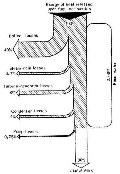
Fig.
11.19