11.5 Regenerative cycle
As in gas-turbine plants,
the thermal efficiency of a steam power plant is raised by means of heat
regeneration.
If a steam power plant is
operated on a Rankine cycle without steam reheating and if complete regeneration
of heat is accomplished, then the thermal efficiency of this Rankine cycle will
be equal to the thermal efficiency of a Carnot cycle. Figure 11.25 shows the
Rankine wet-steam cycle with full regeneration on a T-s diagram (it is
understood that we are speaking of internally reversible cycles).
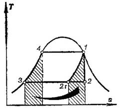
Fig.
11.25
The efficiency of the
Rankine cycle with steam reheating, even with maximum regeneration, will be
inferior to the thermal efficiency of the Carnot cycle in the same temperature
interval: as it follows from the T-s diagram shown in Fig. 11.26, with
the thermal efficiency of the reheat Rankine cycle increasing appreciably,
compared with the cycle without regeneration.
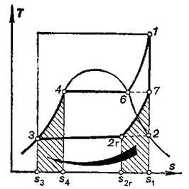
Fig.
11.26
The regenerative cycle
shown in Fig. 11.26 is represented as an ideal cycle: as was shown in Sec. 10.2
equidistant heat addition and heat rejection lines (line 3-4 and line 7-2r, respectively, in Fig.
11.26) can be ensured provided an ideal regenerator is used.
It follows from the T-s diagram
shown in Fig. 11.26 that the thermal efficiency of the Rankine cycle with
maximum regeneration is determined from the expression
![]() (11.110)
(11.110)
In actual steam power
cycles regeneration is effected with the aid of surface-type or direct-contact
regenerative feed-water heaters, either of which is supplied with steam from
intermediate turbine stages (the regenerative takeoff). The steam
condenses in the regenerative feed-water heaters FWH 1 and FWH 2 heating the
feed water which is delivered to the boiler. Heating steam condensate is also
delivered to the boiler or mixes with the main flow of feed water (Fig. 11.27).
Strictly speaking, the regenerative cycle of a steam power plant cannot be
represented on a two-dimensional T-s diagram, since this diagram is
plotted for a constant amount of working medium, whereas in a regenerative
cycle, involving the use of regenerative feed-water heaters, the quantity of
the working medium varies along the turbine
blading. Therefore, in investigating the cycle plotted on a flat T-s diagram
(Fig. 11.28), the hypothetical nature of this representation should be borne in
mind; for emphasis, a diagram representing the rate of steam flow through the
turbine along its blading is shown adjacent to the T-s diagram.
This new diagram pertains to line 1-2 on the T-s diagram, the
line of adiabatic expansion of steam in the turbine. Thus, on the section 1-2
of the cycle, shown on the T-s diagram, the quantity of the working
medium diminishes with a drop in pressure, and along the section 5-4 the
quantity of the working medium increases with rising pressure (heating steam
condensate is added to the feed water).
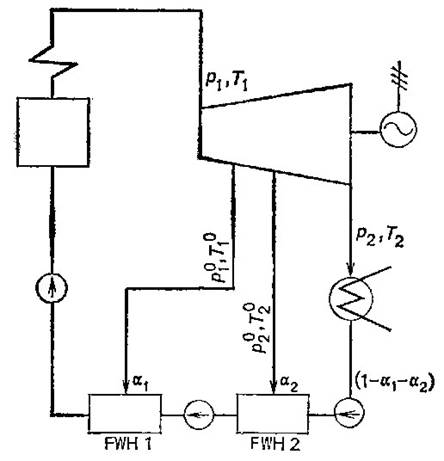
Fig.
11.27
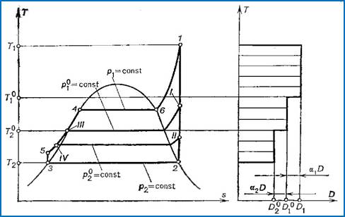
Fig.
11.28
Ideally, the regenerative
cycle should be represented in a three-dimensional system of coordinates: T,
s, D. Figure 11.29 shows a regenerative cycle with two heating stages on a T-s-D
diagram. The T-s diagrams of the cycles realized by three fractions of
the steam flow are shown in the same illustration: the fraction of steam bled
into the first heating stage (![]() ), the fraction of steam bled from the turbine into
the second heating stage (
), the fraction of steam bled from the turbine into
the second heating stage (![]() ) and the fraction passing into the condenser [
) and the fraction passing into the condenser [![]() ]. Since it is rather difficult to make use of the
three-dimensional system of coordinates, they find no practical application.
]. Since it is rather difficult to make use of the
three-dimensional system of coordinates, they find no practical application.
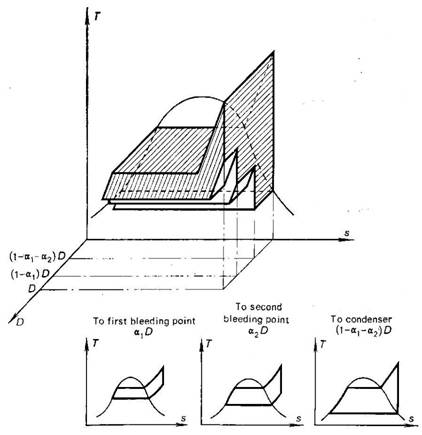
Fig.
11.29
When not surface-type but
direct-contact regenerative heaters are used, in accordance with the layout of
the steam power plant shown in Fig. 11.27, several pumps must be installed,
since water pressure should be increased in steps: the pressure of the water
flowing into a direct-contact heater should be equal to the pressure of the
steam bled for this heater. In the diagram the number of pumps exceeds the
number of steam bleeding points by one.
Let us consider in detail
the cycle of the regenerative steam power plant with two direct-contact feed-water
heaters, depicted in Fig. 11.27 (an internally reversible cycle is
considered). Denote the fraction of the working medium bled from the turbine by
α. If the rate of steam flow at the turbine entry is denoted by D,
then ![]() kg/h of steam is bled from the turbine and directed
into the first regenerative heater FWH1, and
kg/h of steam is bled from the turbine and directed
into the first regenerative heater FWH1, and ![]() kg/h of steam is bled into the second regenerative
heater FWH2.
kg/h of steam is bled into the second regenerative
heater FWH2.
Hence, up to the first
bleeding point D kg/h of steam performs work in the turbine, downstream
from this point ![]() kg/h of
steam performs work, and downstream from the second bleeding point
kg/h of
steam performs work, and downstream from the second bleeding point ![]() kg/h of steam performs work.
kg/h of steam performs work.
Correspondingly, ![]() kg/h of exhaust steam passes into the condenser;
kg/h of exhaust steam passes into the condenser;
![]() kg/h of water (condensate) from the condenser and
kg/h of water (condensate) from the condenser and ![]() kg/h of steam from the second bleeding point are
delivered into the second regenerative heater. As a result of the mixing of
bled steam and condensate
kg/h of steam from the second bleeding point are
delivered into the second regenerative heater. As a result of the mixing of
bled steam and condensate ![]() kg/h of
heated feed water leaves the second regenerative heater. Directed into the
first regenerative heater is
kg/h of
heated feed water leaves the second regenerative heater. Directed into the
first regenerative heater is ![]() kg/h of water from the
second heater and
kg/h of water from the
second heater and ![]() kg/h of steam from the first bleeding point; the
water and steam mix and D kg/h of heated feed water leaves this heater.
The feed water flows to the feed pump which delivers it to the boiler. Let us
find out on what basis the values of
kg/h of steam from the first bleeding point; the
water and steam mix and D kg/h of heated feed water leaves this heater.
The feed water flows to the feed pump which delivers it to the boiler. Let us
find out on what basis the values of ![]() and
and ![]() are selected.
are selected.
The conditions of the steam
bled from the turbine are preset. Let us denote steam pressure at the first
bleeding point by ![]() and the pressure
of steam at the second bleeding point by
and the pressure
of steam at the second bleeding point by ![]() .
.
The pump delivers ![]() kg/h of feed water from the condenser into the
second regenerative heater at a pressure of
kg/h of feed water from the condenser into the
second regenerative heater at a pressure of
![]() . This water is not heated to the boiling
point corresponding to the pressure
. This water is not heated to the boiling
point corresponding to the pressure ![]() ; the temperature of this feed water is
somewhat higher than T2.
Let us denote its enthalpy by
; the temperature of this feed water is
somewhat higher than T2.
Let us denote its enthalpy by ![]() . From the bleeding point
. From the bleeding point ![]() kg/h of superheated steam is delivered into the
heater at the same pressure
kg/h of superheated steam is delivered into the
heater at the same pressure ![]() . Denote the enthalpy of this superheated
steam by
. Denote the enthalpy of this superheated
steam by ![]() . The value of
. The value of ![]() is selected so that the mixing of superheated steam
and water at a temperature below the boiling point will yield feedwater heated
to the boiling point corresponding to the pressure
is selected so that the mixing of superheated steam
and water at a temperature below the boiling point will yield feedwater heated
to the boiling point corresponding to the pressure ![]() . The enthalpy of saturated water at the pressure
. The enthalpy of saturated water at the pressure ![]() will be
denoted by
will be
denoted by ![]() . The heat balance equation for the second
regenerative heater takes the following form:
. The heat balance equation for the second
regenerative heater takes the following form:
![]() (11.111)
(11.111)
The first regenerative
feed-water heater receives water in the amount of ![]() kg/h at a pressure
kg/h at a pressure ![]() ; denote its enthalpy by
; denote its enthalpy by ![]() . Superheated steam flows
from the first bleeding point into the heater in the amount of
. Superheated steam flows
from the first bleeding point into the heater in the amount of ![]() kg/h; denote the enthalpy of this steam by
kg/h; denote the enthalpy of this steam by ![]() . Just as for the second regenerative heater, the
rate of flow from the first bleeding point into the first heater is selected so
that water leaves the heater at the boiling point corresponding
to the pressure
. Just as for the second regenerative heater, the
rate of flow from the first bleeding point into the first heater is selected so
that water leaves the heater at the boiling point corresponding
to the pressure ![]() ; the
enthalpy of this feed water is denoted
; the
enthalpy of this feed water is denoted ![]() .
.
The heat balance equation
for the first regenerative heater takes the following form:
![]() (11.112)
(11.112)
Equations (11.111) and
(11.112) yield:
![]() (11.113)
(11.113)
![]() (11.114)
(11.114)
As a result of regenerative
heating, feed water is delivered into the boiler at a temperature of ![]() , i.e. at the saturation temperature corresponding to
the pressure
, i.e. at the saturation temperature corresponding to
the pressure ![]() . The enthalpy of water in
this state is
. The enthalpy of water in
this state is ![]() . Hence, the amount of heat added in the boiler to
1 kg of working medium is
. Hence, the amount of heat added in the boiler to
1 kg of working medium is
![]() (11.115)
(11.115)
In the condenser an amount
of heat (i2 —
i3)
is removed from each kilogram of steam. However, since we have
shown that from each kilogram of steam entering the turbine only ![]() kilograms of
exhaust steam enters the condenser, it is clear that the heat rejected from one
kilogram of exhaust steam amounts to
kilograms of
exhaust steam enters the condenser, it is clear that the heat rejected from one
kilogram of exhaust steam amounts to
![]() (11.116)
(11.116)
It follows that, in accordance
with the general relationship (9.1), the equation for the thermal efficiency of
the regenerative feed-water cycle with two steam bleedings can be presented in
the following form:
![]() (11.117)
(11.117)
The problem of determining
the thermal efficiency of the regenerative feed-water cycle can also be
approached in another way.
One kilogram of steam
passing into the condenser produces in the turbine the following amount of
work:
![]() (11.118)
(11.118)
One kilogram of steam bled
from the turbine into the second regenerative heater, performs in the turbine
the following amount of work prior to bleeding:
![]() (11.119)
(11.119)
Finally, one kilogram of
steam bled into the first regenerative heater does the following amount of work
in the turbine:
![]() (11.120)
(11.120)
Taking into account Eqs.
(11.118) to (11.120), the work of the regenerative cycle[2]
can be presented in the form
![]() (11.121)
(11.121)
Taking Eq. (11.115) into
account, we obtain from the above formula the following expression for the
thermal efficiency of the regenerative feed-water cycle:
![]() (11.122)
(11.122)
Finally, the work done by
the steam in the cycle will be equal to the work which would be done by 1 kg of
steam without bleeding minus the work which would be performed by the fractions
of 1 kg of steam bled into the heaters (if the fractions
of steam were expanded in the turbine to the condenser pressure):
![]() (11.123)
(11.123)
From Eq. (11.123) we obtain
one more expression for the thermal efficiency of the regenerative cycle with
two steam bleedings:
![]() (11.124)
(11.124)
It is understood that the
three equations for the thermal efficiency of the regenerative cycle, (11.117),
(11.122) and (11.124), are identical.
Of a similar nature are the
equations for the thermal efficiency of the regenerative cycle with any number
of heating stages. In particular, the expression similar to Eq. (11.124) for a
cycle with n heating stages can be written in the form
![]() (11.125)
(11.125)
An analysis shows that an
increase of the number of regenerative heating stages leads to a higher cycle
thermal efficiency, for in this case the degree of regeneration in the cycle
approaches the maximum (Fig. 11.26). However, each subsequent stage of
regenerative heating contributes less and less to the rise in thermal
efficiency, as can be seen from the graph in Fig. 11.30, where the rate of increase in the thermal efficiency of a
regenerative cycle, ![]() , is plotted as a function of
the number of regenerative heating stages, n; the graph is plotted for
the case of uniform distribution of feed-water heating among individual stages.
, is plotted as a function of
the number of regenerative heating stages, n; the graph is plotted for
the case of uniform distribution of feed-water heating among individual stages.
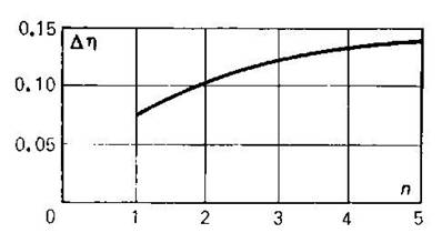
Fig.
11.30
In modern high-power steam
power plants operated at high steam conditions the number of regenerative
heating stages reaches nine.
The selection of bleeding
points on a turbine for supplying steam to direct-contact regenerative
feed-water heaters (i.e. the selection of the temperature to which feed water
is to be heated in each of the heating stages[3])
is the subject for special analysis, a detailed consideration of which is
beyond the scope of this book. It will only be noted that the criterion in
selecting a particular distribution of regenerative heating by stages is to
ensure a maximum economy, usually attained by raising the thermal efficiency
of the cycle. With an infinite number of feed-heating stages the cycle thermal
efficiency is determined unambiguously, but when a finite number of
feed-heating stages is operated, the cycle efficiency will differ depending on
the mode of temperature distribution between individual stages.