11.7 Thermification
cycles
In the process of power
generation in thermal electric power stations, a great amount of heat is
transferred to the low-temperature source, the water cooling the condenser, and
is thus lost. The amount of heat transferred to the low-temperature source, q2, can be decreased by
raising the thermal efficiency of the given cycle. However, this loss cannot be
fully eliminated since, in accordance with the second law of thermodynamics,
the transfer of a certain amount of heat to the low-temperature source is
inevitable.
If it is impossible in
principle to eliminate the transfer of heat to the low-temperature source, then
is this heat unusable? As is known, great amounts of hot water and steam are
used for all kinds of technological processes, for heating buildings and
hot-water supply.
In ordinary steam power
plants with condensing turbines, the condenser pressure is maintained equal to
about 4 kPa (0.04 kgf/cm2), i.e. exhaust
steam condenses at a temperature of about
29 °C. The heat transferred to the cooling water in such a condenser has
a low temperature potential, and it cannot be used for process
work or for heating and hot-water supply purposes. Technological processes
usually need saturated steam at a pressure from 250 to 2000 kPa (i.e. from
about 2.5 to 30 kgf/cm2), and buildings are heated with saturated
steam at a pressure from 150 to 260 kPa (1.5 to 2.6 kgf/cm2). Hot
water at a temperature reaching 180 °C is also used in some installations.
In order to be able to
utilize the heat rejected from the condensing exhaust steam, condenser pressure
must be raised, i.e. it is necessary to raise the temperature at which this
steam condenses. An increase of the lower cycle temperature will result in a
certain decrease in the thermal efficiency and, consequently, in a reduction of
the amount of power generated with the same fuel expenditure as before.
Therefore, from the point of view of cycle effectiveness, such an operation is
disadvantageous. However, the possibility of getting great amounts of heat for
industry and heating purposes by some reduction in power generation is very
expedient (it makes it unnecessary to construct special heating boiler houses,
which as a rule are small and operate with a relatively low efficiency and
require therefore a higher fuel consumption; in addition, such boiler houses
use heat of a high temperature potential, realized upon fuel combustion in
boiler furnaces, to heat a low-temperature working medium, which is irrational
due to the inevitable decrease of system availability).
Electric stations engaged
in the generation of heat and electric power use back pressure turbines or
extraction turbines.
Steam power plants engaged
in combined generation of electric power and heat are referred to as heating
and power plants, as distinct from power plants fitted with condensing
turbines and generating only electric power.
The T-s diagram of a
heating and power plant is shown in Fig. 11.33. As usual, the work of the cycle
is represented by the area 1-2-3-5-4-6-1, and the area A-3-2-B-A
represents the heat q2 transferred to the external
consumer.
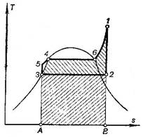
Fig. 11.33
Since, as
was mentioned above, industry and district heating systems require steam and
hot water at a relatively wide range of temperatures and pressures, heating and
power plants use back pressure and extraction turbines of different types,
depending on the nature of heat consumption.
Figure
11.34 shows the schematic diagram of a heating and power plant with turbines
with a deteriorated vacuum. The pressure maintained in the condenser of
such a turbine is such that the vapour saturation temperature is sufficiently
high to ensure the required heating of the cooling water in the condenser. The
cooling water, heated in the condenser to the required temperature, is
delivered to district heating systems.
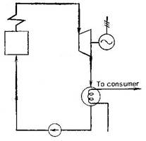
Fig. 11.34
Figure
11.35 shows the schematic diagram of a heating and power plant fitted with back
pressure turbines. In these plants there is no condenser and the exhaust steam,
leaving the turbine, is directed via a pipeline to be used as industrial steam
in apparatuses in which heat is rejected from the steam and the steam
condenses; the condensate is returned to the plant as feed water for the
boilers. The pressure of the exhaust steam leaving the turbine is determined
depending on industrial steam requirements.
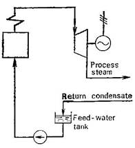
Fig. 11.35
The
heating and power plant depicted schematically in Fig. 11.36 is fitted with
extraction turbines. In this kind of plant steam at quite high conditions is
extracted from intermediate turbine stages (from this viewpoint this layout
resembles the power plant with regenerative feed-water heaters). The extracted
steam can be directed to be used for industrial purposes (so-called industrial
steam extraction), and condensate is returned to the plant (Fig. 11.36a), or to special heaters (heat exchangers; HE) in which this
steam heats water to be used in district heating systems (so-called district-heating
extraction, Fig. 11.36b). It ought to
be mentioned that extraction turbines are most widely used in modern heating
and power plants.
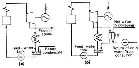
Fig. 11.36
Economic
performance of a heating and power plant is characterized by the heat-utilization
factor K, defined as the ratio of the useful work done in the cycle (lp)
plus the heat transferred to the external consumer (q2) to the amount of heat
released upon fuel combustion in boiler furnaces, q1:
![]() (11.128)
(11.128)
or, which is the same,
![]() (11.129)
(11.129)
where N is the electric capacity of the power
plant, B the hourly fuel
consumption, Q1 the lower calorific value of fuel, and
Q the amount of heat
transferred to the external consumer.
The more perfect the
plant, the closer is the heat-utilization factor K to unity, i.e. the
least amount of heat losses in the boiler unit and turbine and the mechanical
and electrical losses in the generator.