3.1 Cycles.
Concept of thermal efficiency. Heat sources
In Chapter 2 it was shown that in the process of expansion a gas
performs work expended to overcome the forces of external pressure. In
accordance with Eq. (2.5a), the work performed by a gas undergoing expansion from pressure p1 to pressure p2 is equal to
 (3.1)
(3.1)
where V1 and V2 are the volumes of the gas
at the beginning and end of the process of expansion.
For this process of expansion to be repeated and to obtain the work ![]() again, the gas
must be returned into its initial state 1, characterized by the properties p1 and V1 i.e. the gas must be
compressed. The gas undergoes then a cyclic process or a cycle.
again, the gas
must be returned into its initial state 1, characterized by the properties p1 and V1 i.e. the gas must be
compressed. The gas undergoes then a cyclic process or a cycle.
To compress a gas, naturally, work must be expended and this work is transferred
to the gas from some external source. In accordance with the general
definition, this work is
 (3.2)
(3.2)
or,
which is the same
 (3.3)
(3.3)
The similarity between the expressions for the work of expansion and
compression is illusory: the work depends on the path followed by the process
between the same points 1 and
2.
It is then clear that the compression of a gas from pressure p2 to pressure p1 should be carried out,
following a path different from the path of expansion. Otherwise, the work of
expansion will be equal to the work of compression, and the total work obtained
as the gas undergoes a cyclic process (or simply a cycle) will be equal to
zero. The work expended by a system per one cycle (we shall refer to it as the
work output of a cycle) is equal to the difference (algebraic sum) between the
work of expansion and the work of compression. It is clear that the path of
compression should be selected so that the absolute value of the compression
work is somewhat less than the work of expansion, otherwise the work output of
the cycle will be negative, i.e. no work will result from the cycle but only
spent, though, as it will be shown below, in certain cases the cycle is
organized in exactly this way (refrigeration cycles).
Cycles which result in an output of work are realized in various heat
engines. By a heat engine is meant a continuous acting system operating
in a cycle and converting heat into work. The substance used to obtain work in
a cycle by changing its state is called the working medium (or fluid).
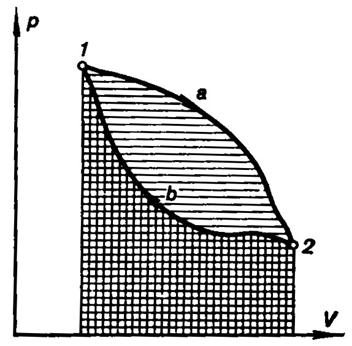
Fig. 3.1
The work output of a cycle is conveniently interpreted in a p-V diagram,
as illustrated in Fig. 3.1. If 1-a-2 is the path of the
process of expansion and 2-b-l the
path of the process of compression, then the area bounded by the curve 1-a-2 is equivalent to expansion work, and
the area below the curve 2-b-1,
to the work of compression, while the area confined within the closed
curve (path of cycle) 1-a-2-b-1 represents the work output of the cycle.
It is clear from this state diagram that for the work output of a cycle to be
positive, the path of the process of compression must be located on the p-V diagram
below the path of expansion. Let us integrate the differential equation of the
first law of thermodynamics
dQ
= dU + dL (3.4)
for an
arbitrary cycle realized by a working medium:
![]() (3.5)
(3.5)
It will be recalled that Q is the amount of heat added to the
system from the outside (or removed from it),
and L denotes work done by the system (or done
on the system). Inasmuch as internal energy U is a function of state
and, consequently, its integral along a closed path is equal to zero (i.e. as the working medium returns into its initial state upon completion of the
cycle, the internal energy of the working medium
acquires its initial magnitude), we obtain
![]() (3.6)
(3.6)
Denoting
![]()
and
![]()
we can
present relationship (3.6) in the following form:
Qc = Lc, (3.7)
i.e.
the work output of a cycle, Lc, is equal to the amount of heat
added to the working medium from an outside source. In accordance with the
first law of thermodynamics, Eq. (3.7) indicates that the work produced by an
engine is equal to the amount of heat removed from an external source and added
to the working medium of the engine. If it were possible to construct a heat
engine in which the amount of work produced would be greater than the amount of
heat added to the working medium from an external source, it would mean that
the first law of thermodynamics (the law of conservation and conversion of
energy) is invalid. From this it would follow that it is possible to construct
a heat engine in which work would be accomplished without any addition of heat
from the outside i.e. a perpetual motion machine[1].
The first law of thermodynamics, therefore, can be formulated as follows:
A perpetual motion
machine of the first kind is impossible.
As regards the heat Qc that is converted into work, it
should be noted that in some parts of a cycle heat is added to the working
medium and removed from it in other parts. As it will be shown below, the
removal of a definite amount of heat from the working medium in some parts of a
cycle is obligatory for the realization of the cycle of any heat engine.
Denoting the amount of heat added to the working medium in a cycle by Q1 and the amount of heat removed from the working medium in a
cycle by Q2, we come to an obvious result:
Qc = Q1 – Q2 (3.8)
and, in
accordance with Eq. (3.7),
Lc = Q1 – Q2. (3.9)
Let us introduce a new concept of the so-called thermal efficiency of
a cycle, by which is meant
the ratio of the work output of a cycle to the amount of
heat added to the working medium during the cycle. Denoting the thermal
efficiency of a cycle by ηT, in
accordance with the definition given above, we obtain:
![]() (3.10)
(3.10)
or,
which is the same,
![]() (3.11)
(3.11)
Accordingly, for 1 kg of the working medium,
![]() (3.12)
(3.12)
or
![]() (3.13)
(3.13)
where l
and q represent the work and heat per 1 kg of the working medium.
The thermal efficiency of a cycle characterizes the degree of perfection
of the cycle analyzed: the higher the thermal efficiency, the more perfect is
the cycle. With an equal amount of heat Q1 added to the working medium, more work Lc is done in the cycle whose
thermal efficiency is higher.
When considering processes involving the addition and rejection of heat
in a cycle, a question naturally arises: Where does the heat Q1 added in the cycle
come from and where is the heat Q2 rejected from the working
medium taken to? In this connection let us introduce the concept of heat
sources. The system from which the heat Q1, added
to the working medium, is removed will be referred to as the high-temperature
source, and the system to which the heat Q2, rejected
from the working medium, is transferred, as the low-temperature source, or heat
sink. For the sake of convenience, it will be assumed below that the total heat
capacity of the high- and low-temperature sources is so great that the removal
of heat Q1
from the high-temperature source and the transfer of heat Q2 to the low-temperature
source does not result in any appreciable change in the temperatures of the two
heat sources.
A detailed analysis of the thermodynamic regularities governing the
performance of work during the cycles developing in heat engines will be made
in the following chapters.
So far, in this section we have been considering cycles on the p-V diagram
in which the path of the process of expansion runs higher than the path
representing the process of compression, i.e. cycles where work is done and
then transferred to an external consumer (Fig. 3.2a). Such cycles are called
forward, or direct, cycles. As it was shown above, in a forward cycle an amount
of heat Q1
is removed from the high-temperature source and an amount of heat Q2 is added to the
low-temperature source, and the difference between these two, Q1 — Q2, is converted into work Lc = Q1
— Q2.
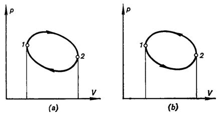
Fig. 3.2
But if a cycle is realized in a way such that the path of the process of
compression is arranged higher than the line representing the process of
expansion (Fig. 3.2b), then, inasmuch as the work of compression happens now to
be greater than the work of expansion, for such a cycle to be accomplished work
must be transferred from some external source of work (the magnitude of this
work, of course, is equal to the area between the paths of expansion and
compression in the p-V diagram). A reverse cycle results in the removal
of heat from the low-temperature source and addition of this heat to the
high-temperature source. Denoting, by analogy with the forward cycle, the heat
removed from the low-temperature source by Q2 and the heat added to the high-temperature source
by Q1 it
is clear that Q1
= Q2 +
Lc. The heat Q1 transferred to the
high-temperature source during the reverse cycle is equal to the sum of the
heat removed from the low-temperature source, Q2, and the heat equivalent to the amount of work added
during the cycle, Lc. Thus
a reverse cycle results in cooling the low-temperature source. The reverse
cycle is the working cycle of a refrigerating unit (machine).